
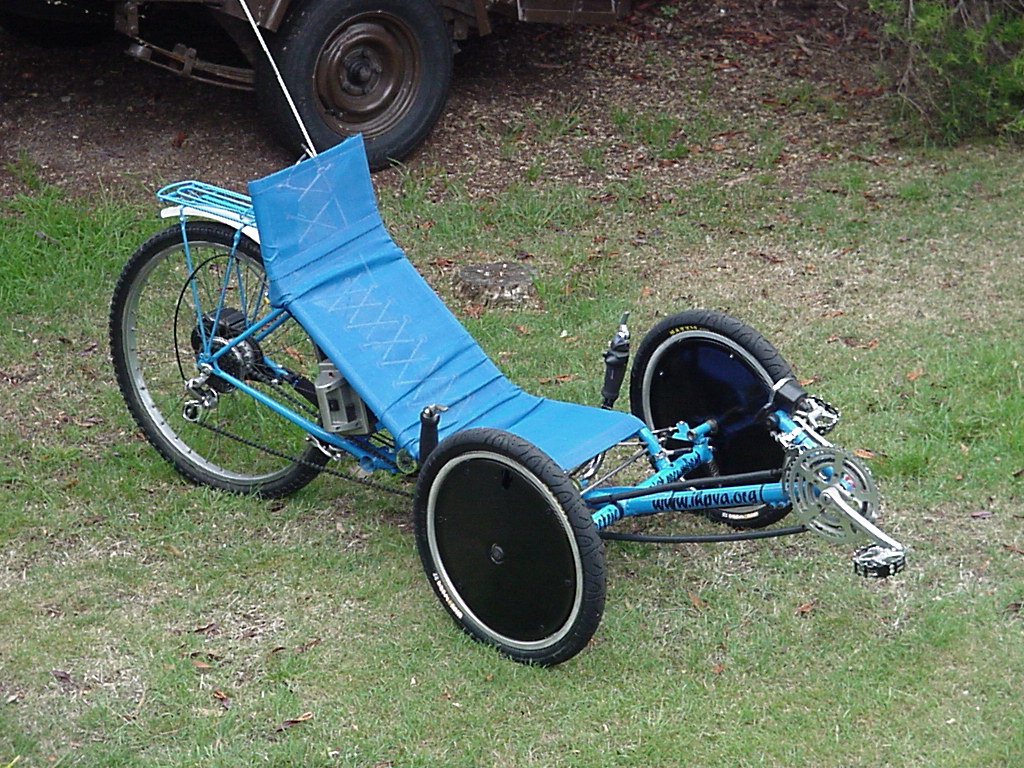
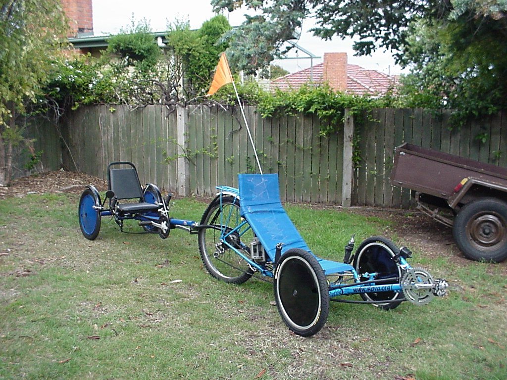
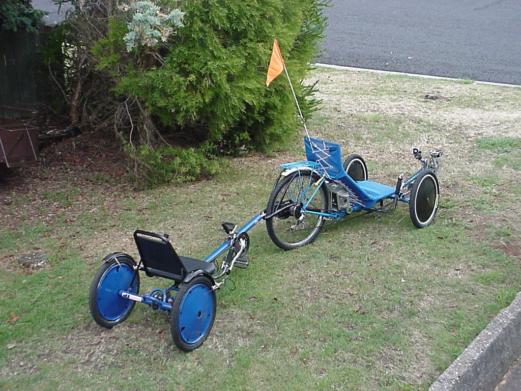
USS Tadpole Electric Power Assisted Trike
This
web page shows as much as possible the construction of this trike including closeup photo's of individual parts. Click on the small pics and that will take
you to much bigger ones - hold your mouse over the pictures first
and it should show the file size of the bigger pic as they are
rather large. There's a lot of pictures linked on this web page
so here's
a web page with them all
inline if that's easier to use.
Along with this description of how to make the trike you may also like to refer to the Web site 'Recumbent Cycle Component Design & Construction' for detailed options on building components.
All of the welding is done with a MIG as it was available. Here is some handy welding info. This seems to be quite strong and works well but takes a bit of practice to get a good looking weld, especially if you want a continuous looking weld right around a joint. Tacking the work before the finishing weld seems mandatory, not only to give time to check your work but also the heat tends to flex each part. I have limited knowledge on other forms of welding so can't comment on their suitability but I do notice most builders seem to use TIG or brazing.
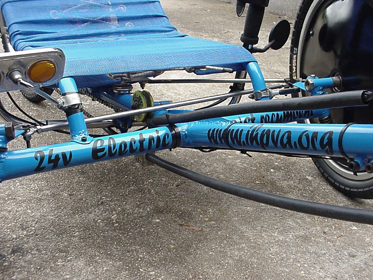
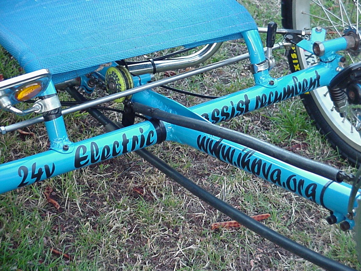
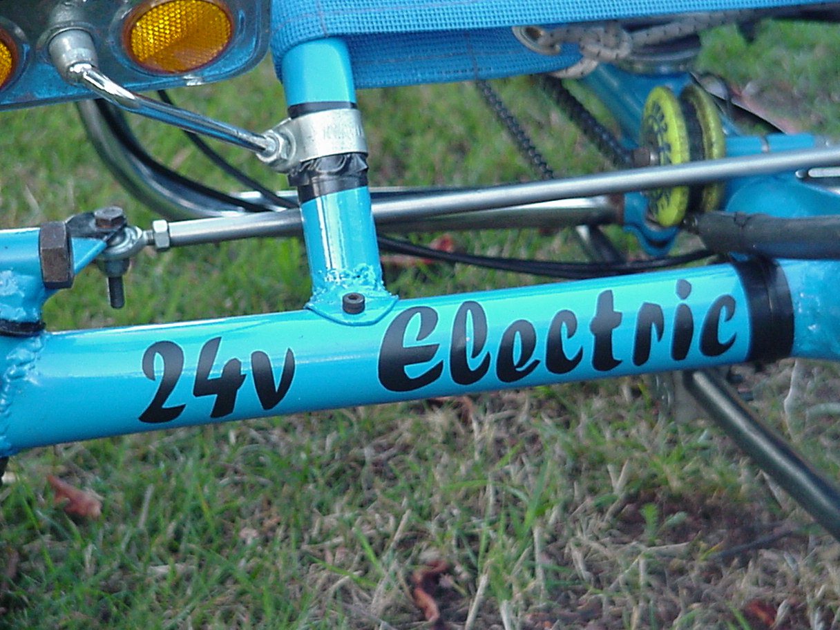
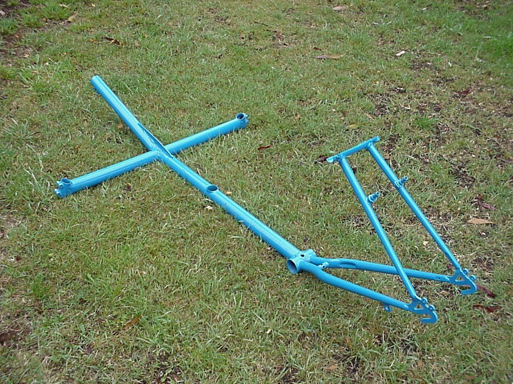
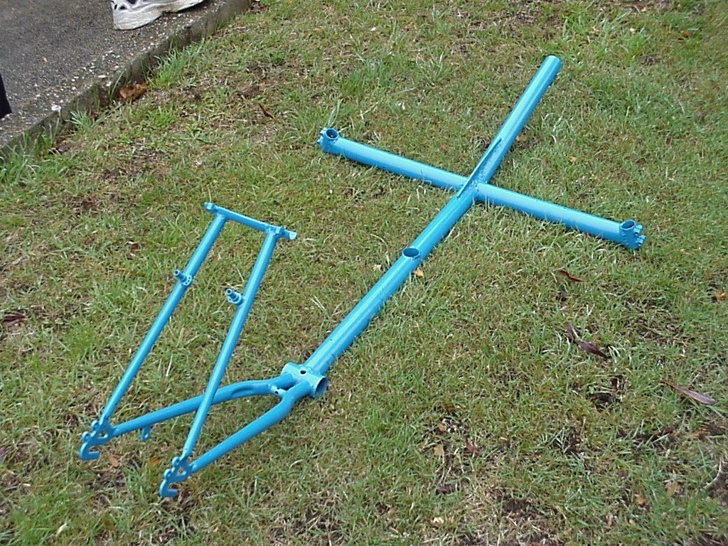
The aim was to build an electric assisted recumbent using as much as possible existing cycle parts or readily available cheap material. To this end the front hubs are from an old wheelchair, the rear frame was taken from a donor 26" bike and the seat made out of (believe it or not) parts of 6 ladies bike frames. The handlebars taken from an exercise bike and the boom and cross member are car exhaust tubing. As I find it hard to afford the gas bottle hire for the MIG welder I tried out the gasless wire available with mixed success. The weld certainly aren't as pretty but hopefully are just as strong.
The US Pro Drive electric assist gives a range for me of about 35 k's including some pedaling with the trike running at approx 25 k/hr on flat ground without pedaling. I can't believe how powerful it is. Top speed without assist so far is 55k/hr and it handled faultlessly. With the present gearing I'm mostly riding in the last 2 gears when at full throttle. What surprised me is it takes a completely different riding style to my other unassisted recumbents. The big difference for me is the extra speed - I can no longer ride easily along the local bike paths here as they are quite rough and uncomfortable when traveling over 12 k/hr so I mostly keep to the road. The assist has so much acceleration I can keep up with the cars in the town centre so rarely ride on the footpaths unlike before.
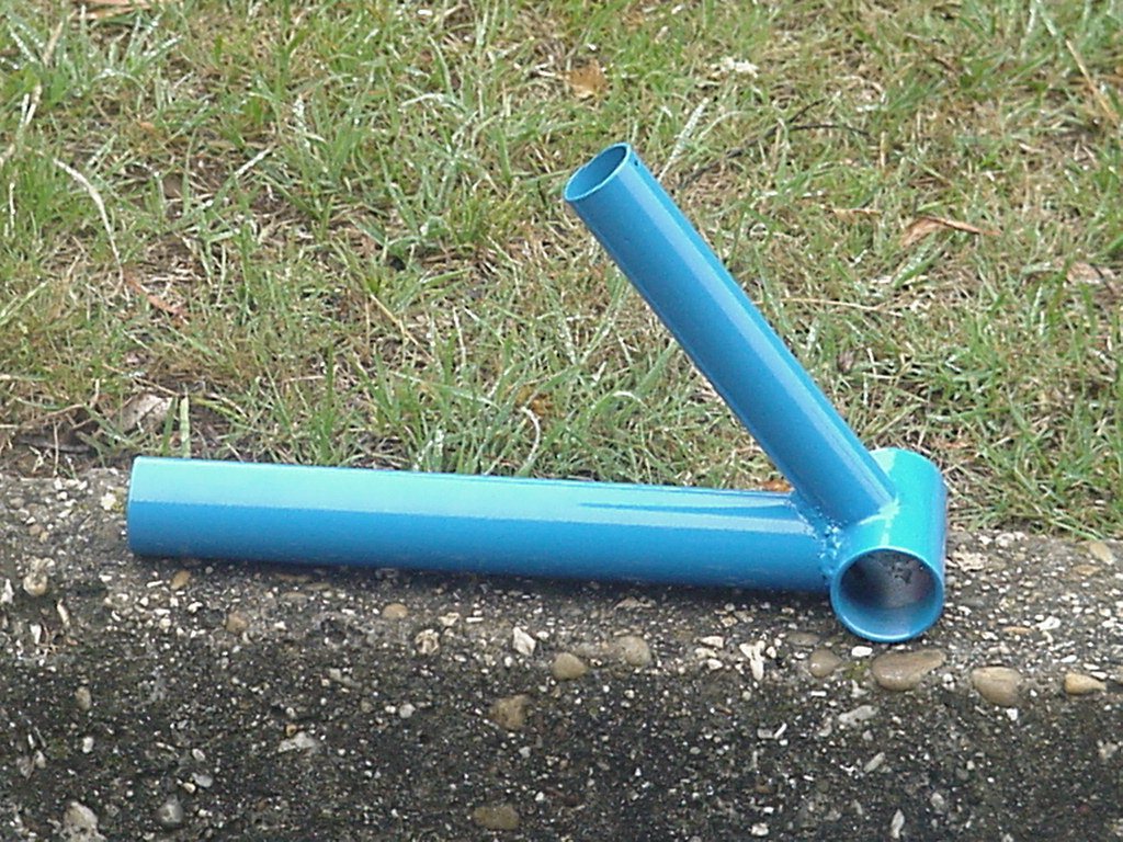
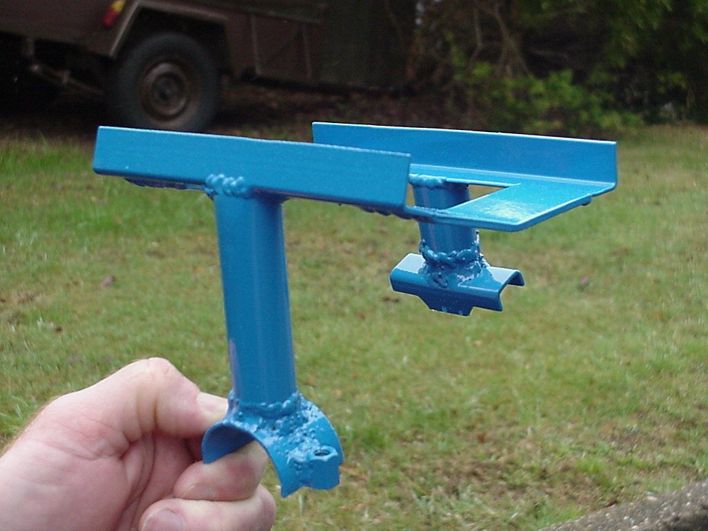
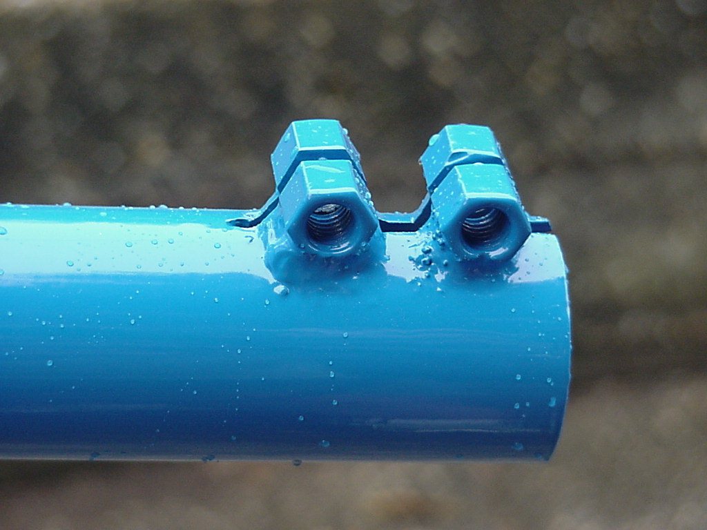
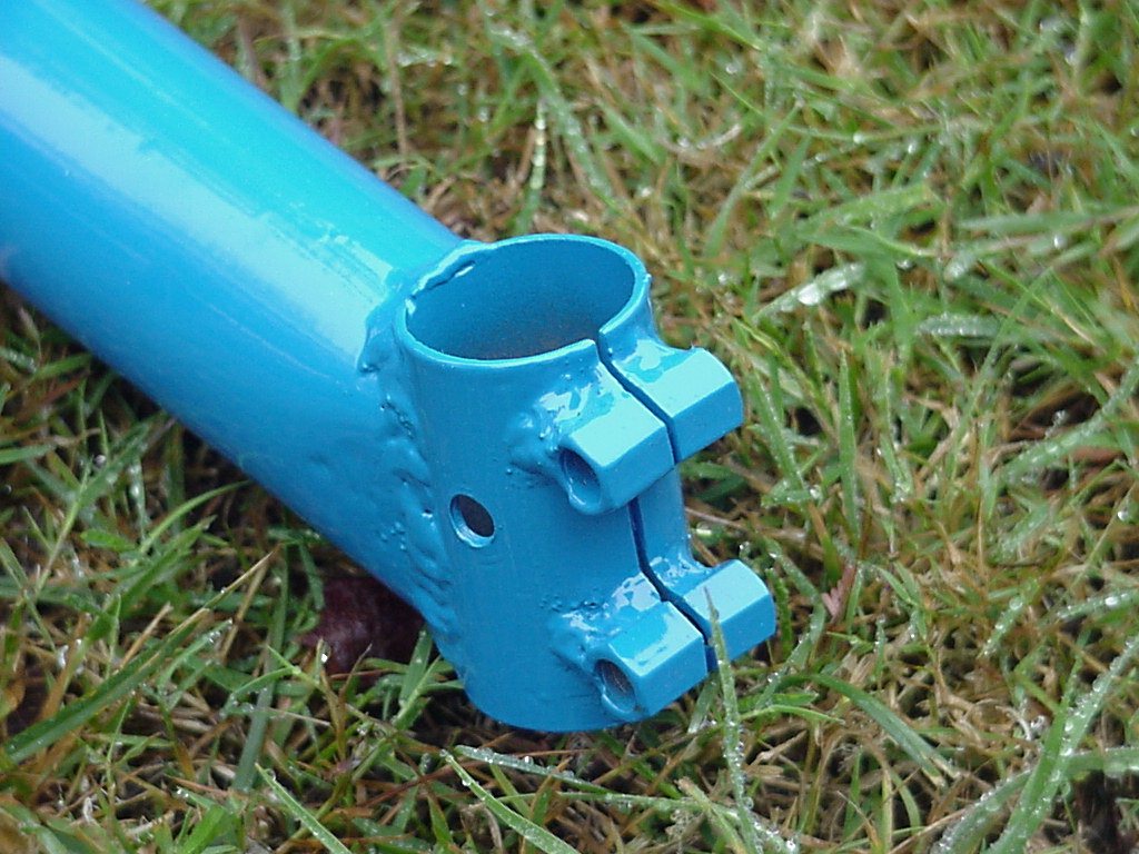
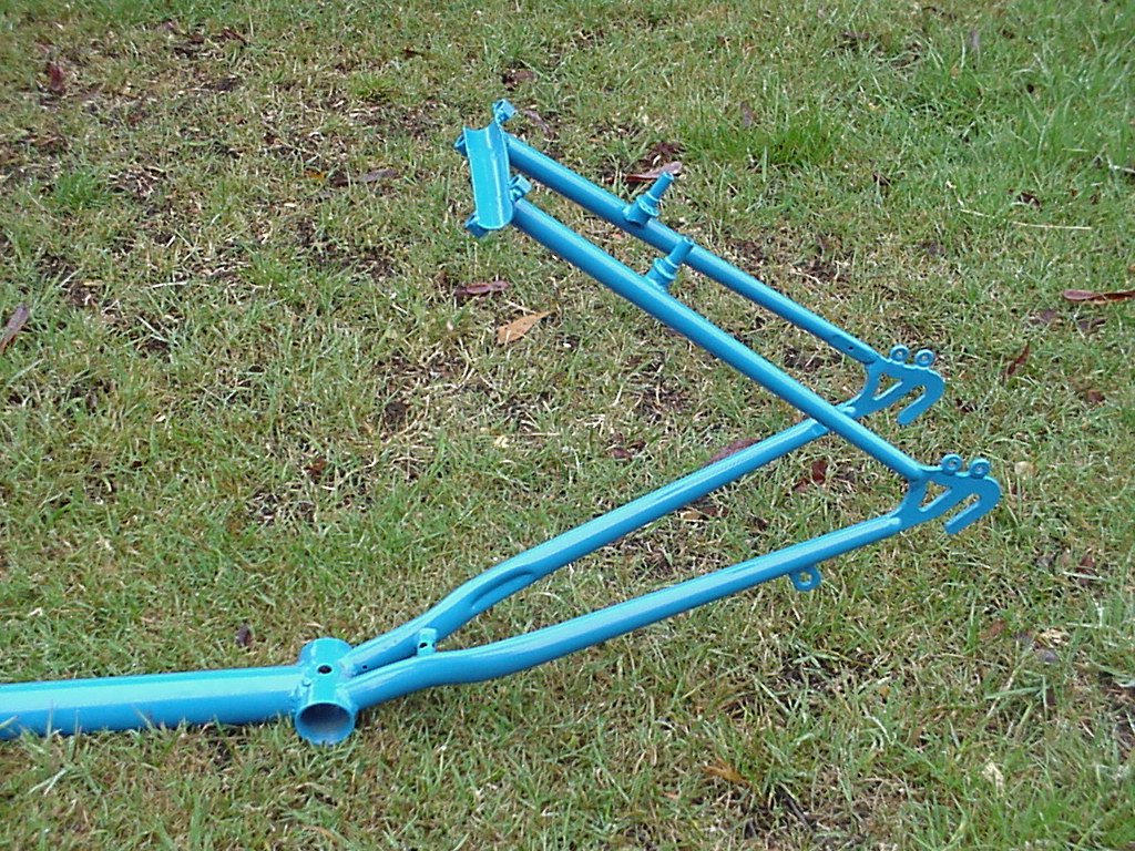
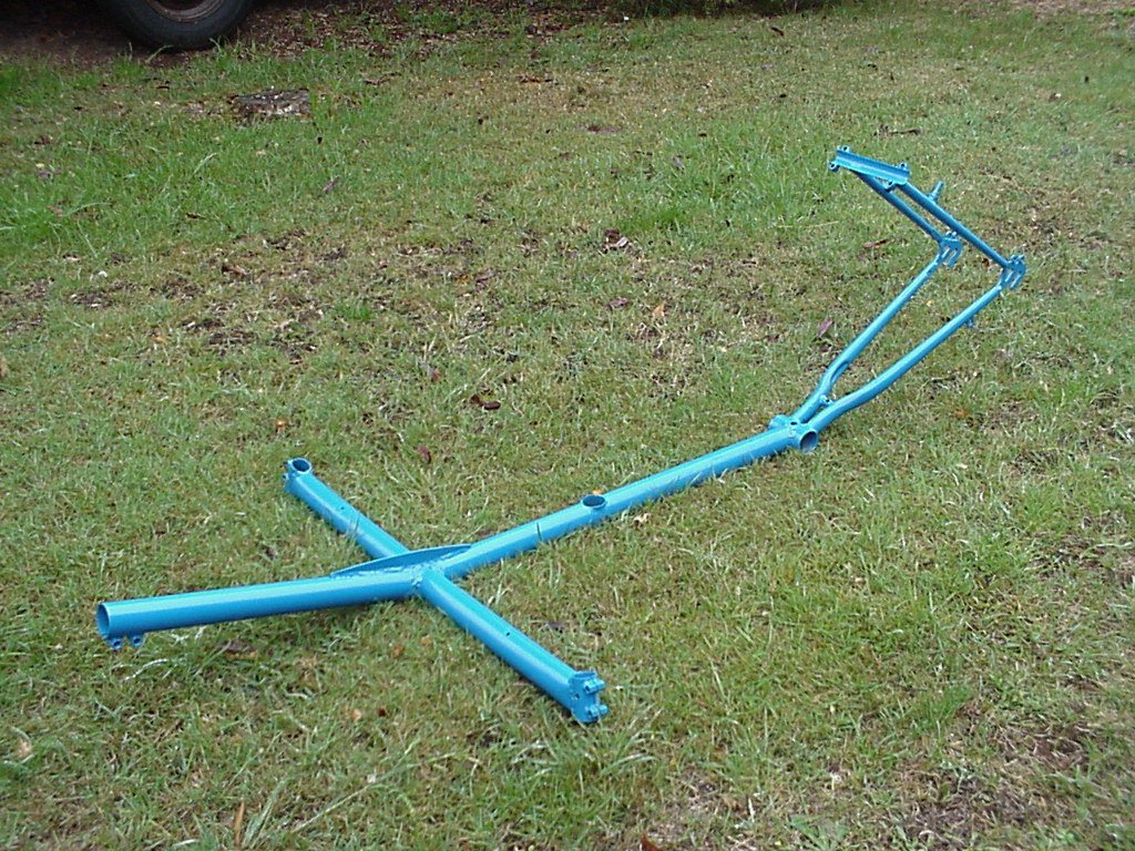
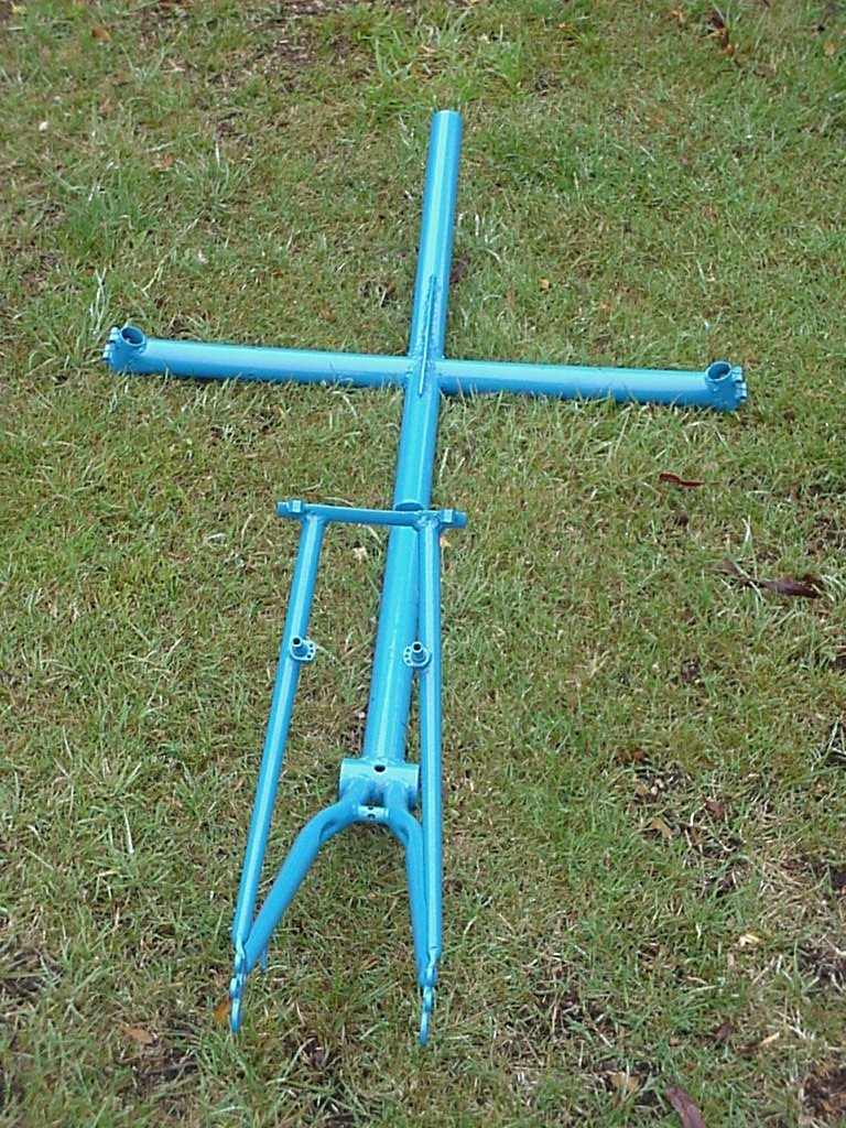
The cross-member is one piece with the boom mating to it. I file the 'fish mouth' cut using a round type file but there are other options using a holesaw, template's etc. Alternatively you could make the cuts with a metal hole-saw. You may find it best to make a jig to hold it all in the exact angle for welding. It could be as simple as blocks of wood fastened to the base board that hold the tubing in place. Some have been known to tack weld the tubing to a metal table/plate to keep it in alignment grinding off the tacks when it's welded. Because I usually make a different machine each time I tend to just use clamps and simple jigs and make sure it is all aligned before finishing the welds. Take the time to get it right, check and double check.
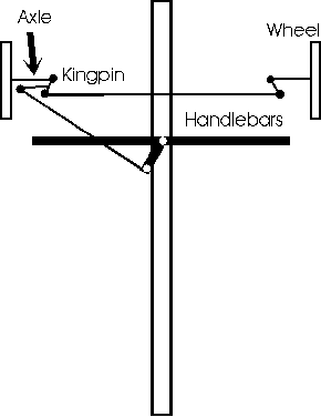
I've always been
concerned with the design many commercial recumbent trikes use
for the steering as they have quite a lot of obstructions passing
across the chain line. They also have many pivot points as part
of the steering system (EG rod ends) which give the chance for
error and slop to occur, especially affecting the toe-in so this
is an attempt to design as much of this out as possible. 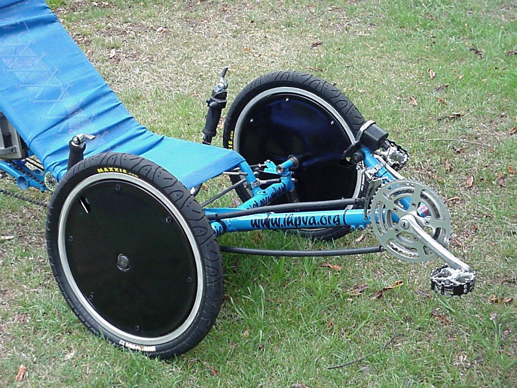
This steering design uses a conventional way to join the wheels with a track arm on both kingpins connected by a rod and rod-ends. The U shaped USS handlebars are similar to say a Greenspeed but the steering is activated on the left side by a rod to a track arm on the back of the kingpin similar to left side only of a Trice Micro. Here's a 5 second video showing the steering movement. 475k, MPEG format, viewing size 320 x 200. To get the track arm angles correct go to Peter Elands Spreadsheet for Ackerman steering design or download the one specifically for this steering.
There are limitations with my design however - When the handlebars are turned fully right they come up against the control rod at full travel. This gives slightly less steering movement than I would like and steering right has a bigger turning circle than left but it is acceptable all the same. If you wanted to try other designs check out the ones listed here.
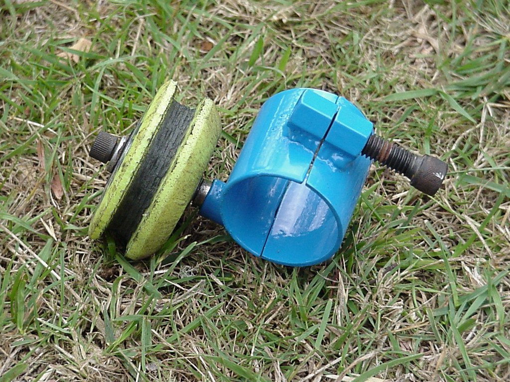
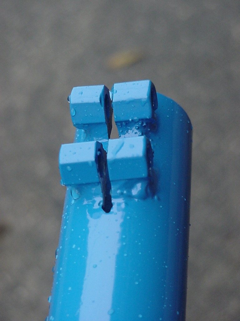
Material - All the parts of the handlebar mount are from an old bike apart from a small ring turned up on a lathe to hold the rear bearing race. The handlebar clamp was cut from a bike steering neck and the handlebars themselves are several cycle handlebars welded together.
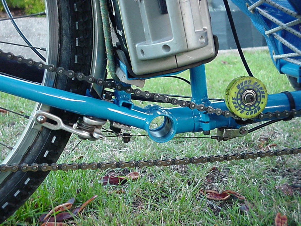
Chain
guides are inline skate wheels - I hope they're tough enough as I haven't used this
before, preferring to use skate wheels but these do look thinner
and neater. The plastic lower chain tube holder (made from a
household cutting board) is about the lowest part of the machine - so
much so that it does touch some speed bumps but is necessary as
the when the chain is under least tension it slightly touches the
handlebars.
part of the machine - so
much so that it does touch some speed bumps but is necessary as
the when the chain is under least tension it slightly touches the
handlebars.
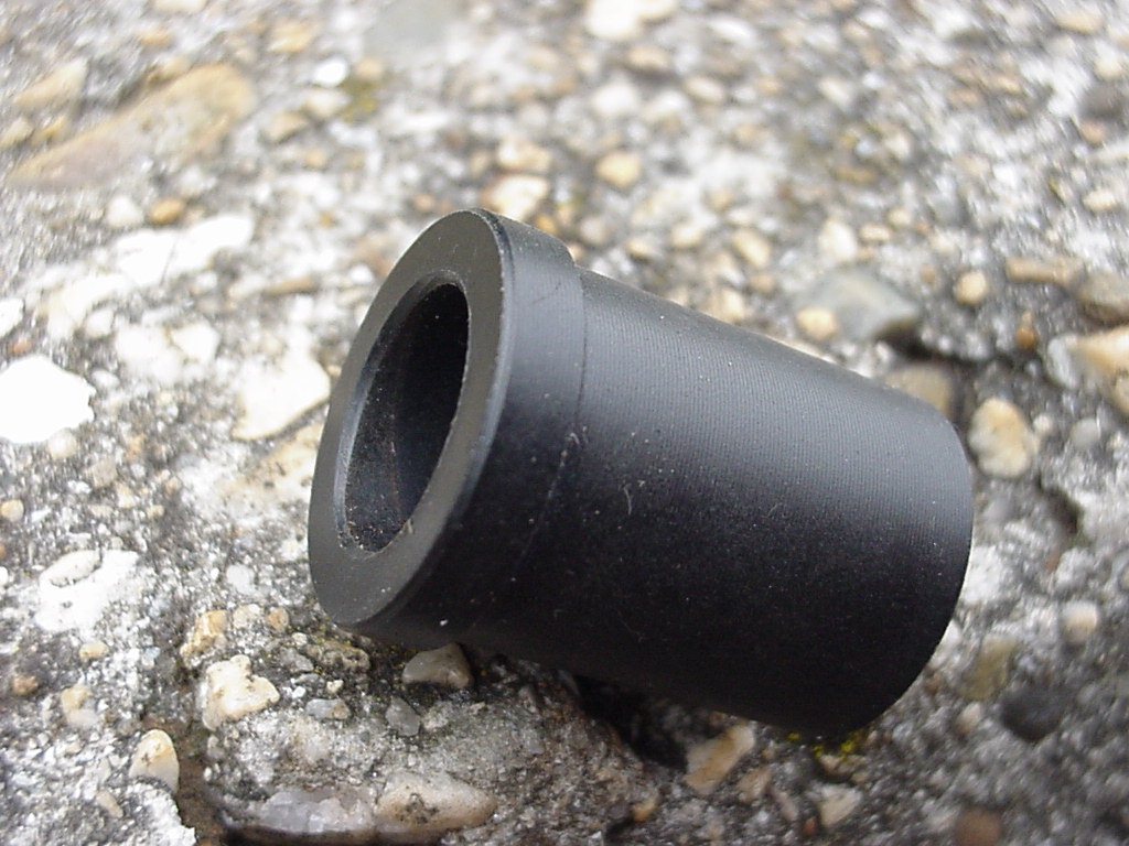
To stop the chain rubbing grease on your legs run the chain through a tube. See 'Some idle thoughts on recumbent chains' & Using Plastic tubing to guide the Chain as well as Lower chain guides.
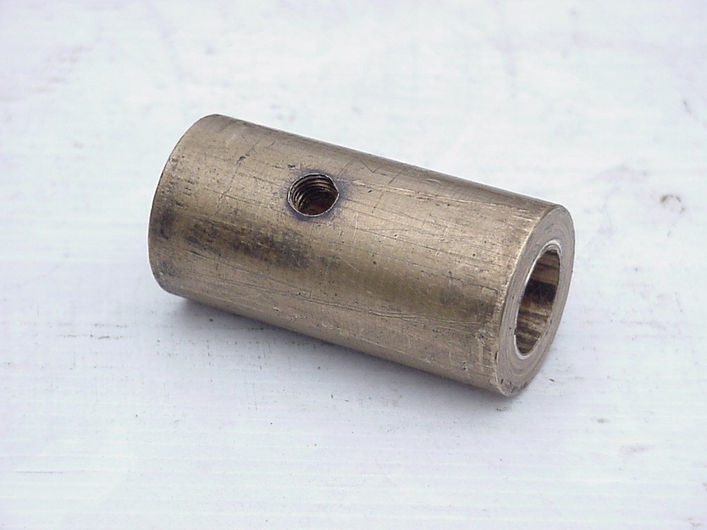
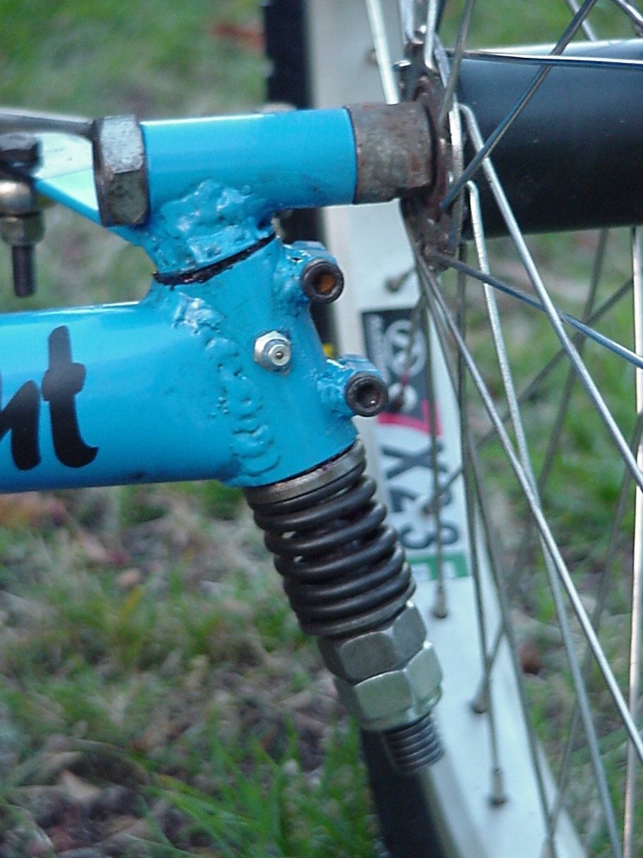
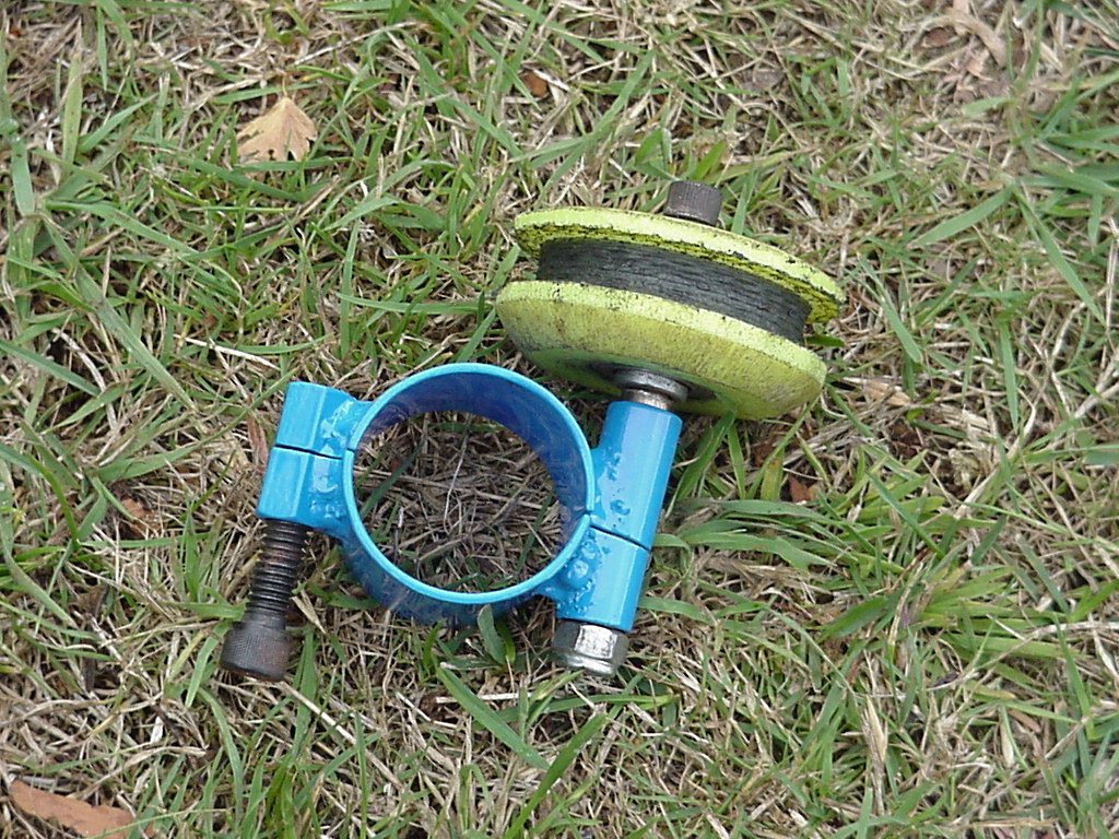
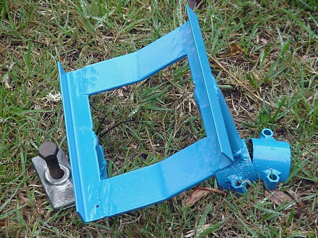
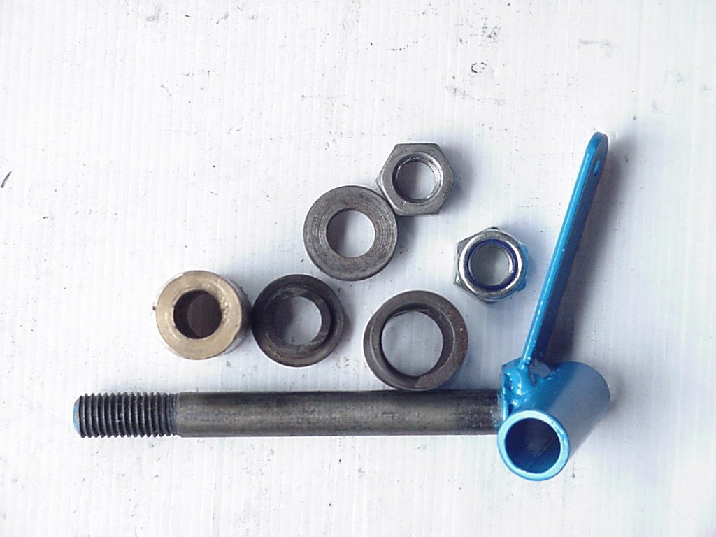
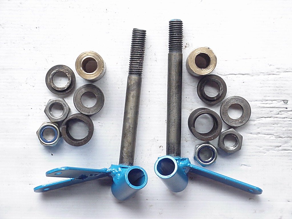
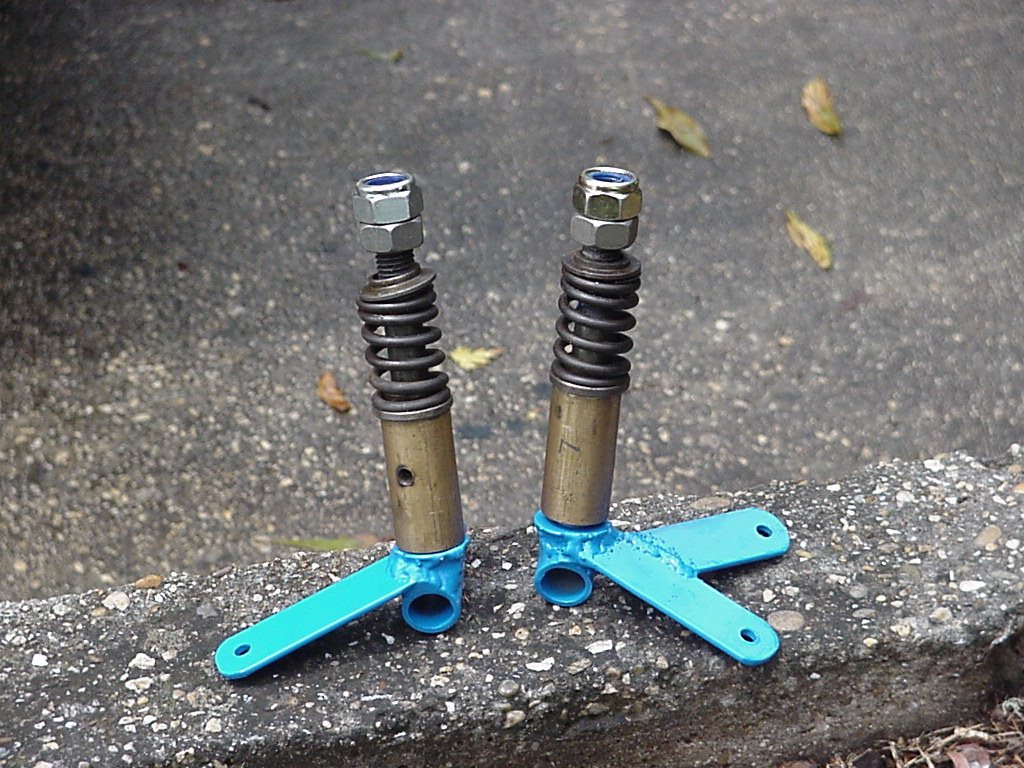
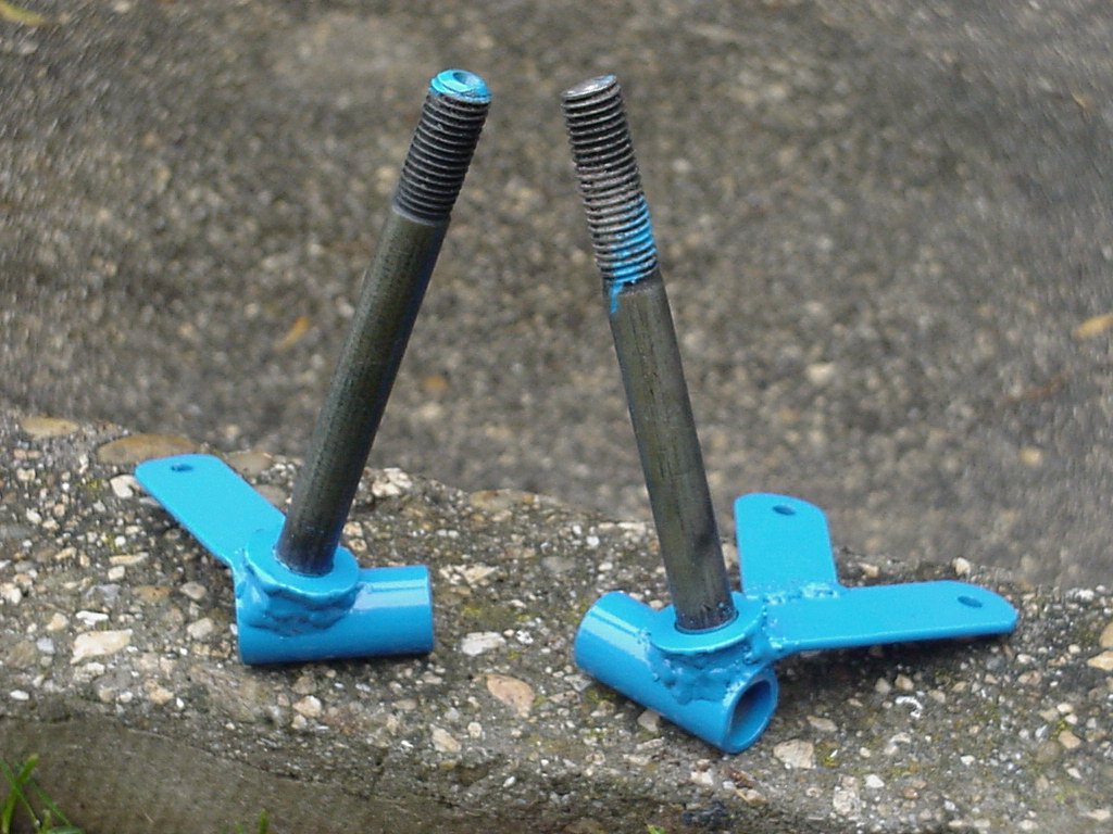
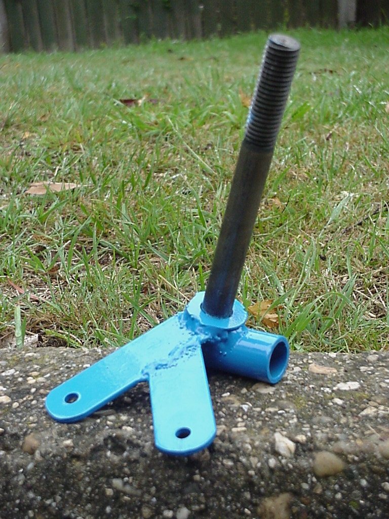
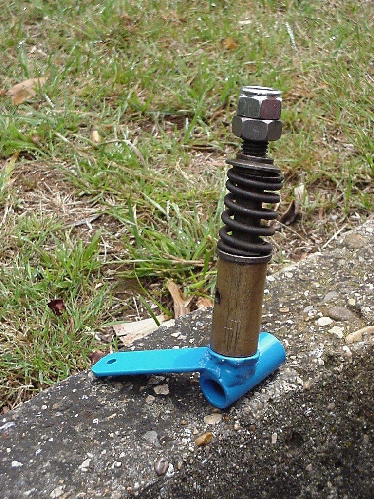
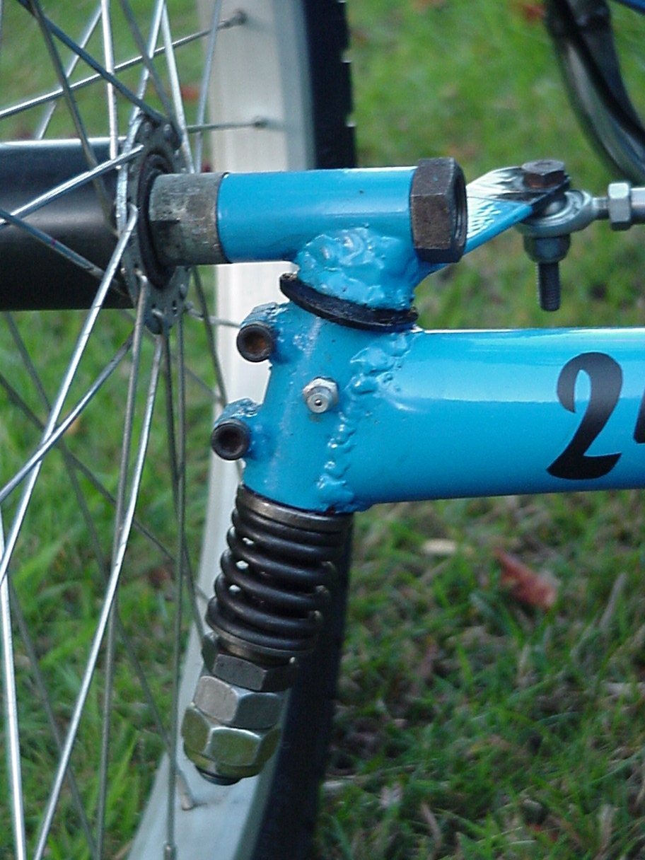
Basically the kingpin has a brass bush for the pivot bearing, a car valve spring for suspension and a hardened bolt for the kingpin. I've not gone this way before usually opting to use old cycle headset bearings and to be honest it would be hard for me to use a brass bush system again as it takes so much longer to make for no gain. As the kingpin is upside down I'd be a bit nervous about the thread letting go when using cycle headsets though. I've seen this done before and not heard any problems but all of the riders weight as well as the trike is holding on by the thread so thee is potential for it to strip. I've certainly seen many stripped threads on 'normal' bikes so it does happen.
I had enormous problems understanding sizing for the bush and bolt. Maybe many of you know this but you can't by a bolt and bush of the same size as there is just way too much slop. To make it worse bolts aren't perfectly round out smooth making their fit inside the bush no so brilliant.
Some manufacturers Eg available from Trisled use a plastic style of bush for the kingpin bearing but I wasn't sure it'd wear so good because of the suspension. Greenspeed sell/use a 5/8" ID bush that takes a 16mm hardened bolt very nicely. Press into 3/4" tubing which is usually the ID of a bit of scrap handlebar tube. I've heard they are bronze, possibly a porous sinter like Oilite. The kingpin they now sell is also much smoother/rounder than a bolt, the problem one may have purchasing them though is in the length as they don't also incorporate suspension travel.
Because I had the bushes I opted for a one piece bronze bush and hardened bolt reaming out the bush to fit the kingpin/bolt exactly. My guess is using the 2 part bush as most others do could make problems for the suspension as the bushes are usually just pressed into the tubing holding them,. The bush at the top could therefore lift out when the suspension compresses and as they have very little material to them it may be hard to clamp/hold them in place. Some have said a one piece bush is best with a spiral groove running through it to allow the grease to travel and push out unwanted material. I wasn't able to do that bit I did add grease nipples.
The issues that have come up with my kingpin/front suspension combo for me are:-
* You have to allow for
suspension travel for the heel to ground clearance when designing
the frame. (and of course trike ground clearance) In other words,
as the suspension allows the trike to drop on bumps parts of the
trike and rider get lower to the ground.
* There may be more wear on the kingpin with suspension because
dust can penetrate easier. I'm on the lookout for a concertina
rubber boot but at the moment I use a modelling baloon?
* The strength of the valve spring is important as you could
imagine.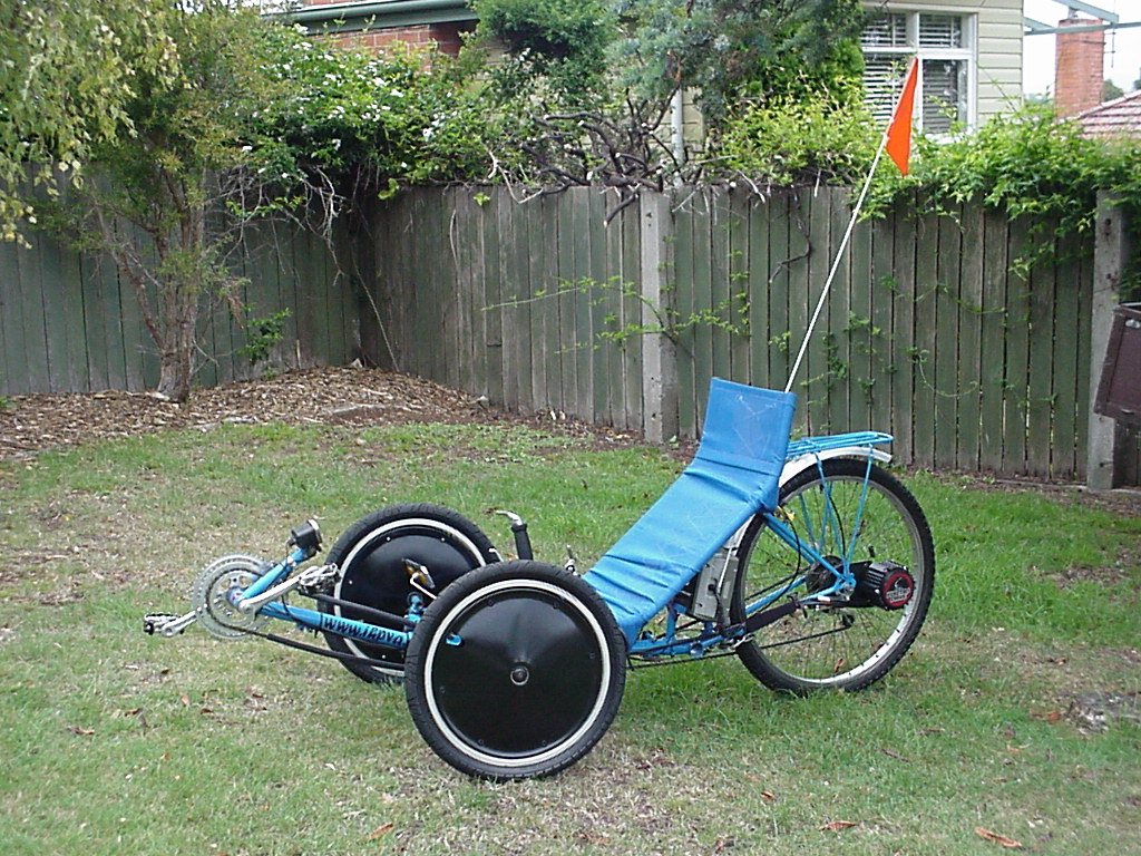
* When the suspension moves, toe in is affected. By how much
depends on the kingpin inclination angle and suspension travel
but make sure you check your toe in with the weight of the rider
on the trike. The adjustment I have finalised on is to have the
pre-load on the spring just enough so that when the rider is
seated there is no suspension movement. What you say, then you've
hardly got suspension? Yes well at the moment there is too much
affected EG toe in and I'm happy with the shock/bump release this
setting gives.
* I find annoying the clicking noise of the suspension topping
out when riding. (as I have quite a hard spring and set for min
travel) Maybe a rubber/felt washer would help but no luck so far.
Rubber washers get chewed out too quick.
* In a sharp turn the suspension does compress and depending on
the stiffness and travel, the trike can body roll away from the
turn slightly/more than without suspension.
This part of the trike does take
quite a lot of time to get right but if you do spend the effort
it will work much better in the long run. Because this is a one
off for me I try to make as much as possible things insitu. So
for example, to make sure the front wheels are vertical (have no
camber) I prop up the trike frame, put the wheel axle tubes onto
the kingpin bolt and run a rod from one side to the other. As
long as the kingpin bolts are the same height and the rod is
straight the wheels have to be vertical. The tubes are tack
welded before pulling them out and fully welding them. The
positioning left/right of the wheel axle tubes very much affect
the steering relating to why we set kingpin inclination. If this
is new to you it worth doing some reading before you start to
build a trike. I won’t go into any detail about the theory
of steering geometry as there are existing sites on the web that
can explain it much better than me.
In a nutshell (Kingpin inclination) the kingpin needs to be
angled so that the line it takes passes a point where the tire
contacts the road. The track arm angle (Ackerman compensation) is
set on the same line drawn front the kingpin pivot to the rear
tire contact point on the ground. The steering axis (castor) is
angled back something like 11 degrees.
Try http://www.ihpva.org/com/PracticalInnovations/design.html for explanations of this. Also worth a
look is Automobile Ride, Handling, and Suspension
Design With Implications for Low-Mass Vehicles. and Three-Wheelers in Automotive Application, Primary
Factors That Determine Handling Characteristics and Aust Intl Pedal Prix constructors guide and building/frontend.htm
What I found helpful was to allow a little more overhand on the wheel side of the kingpin for the axle tube. The aim is to have the projected line of the kingpin hit directly inline with the cente of the wheel where it's sits on the ground. The axle tube can easily be cut off if a little long to fine-tune this setting.
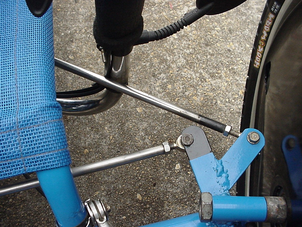
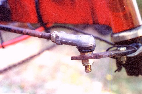
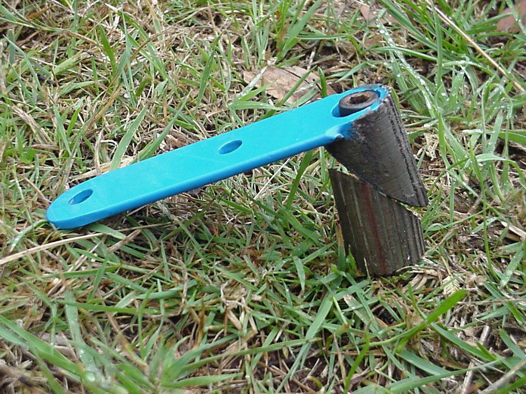
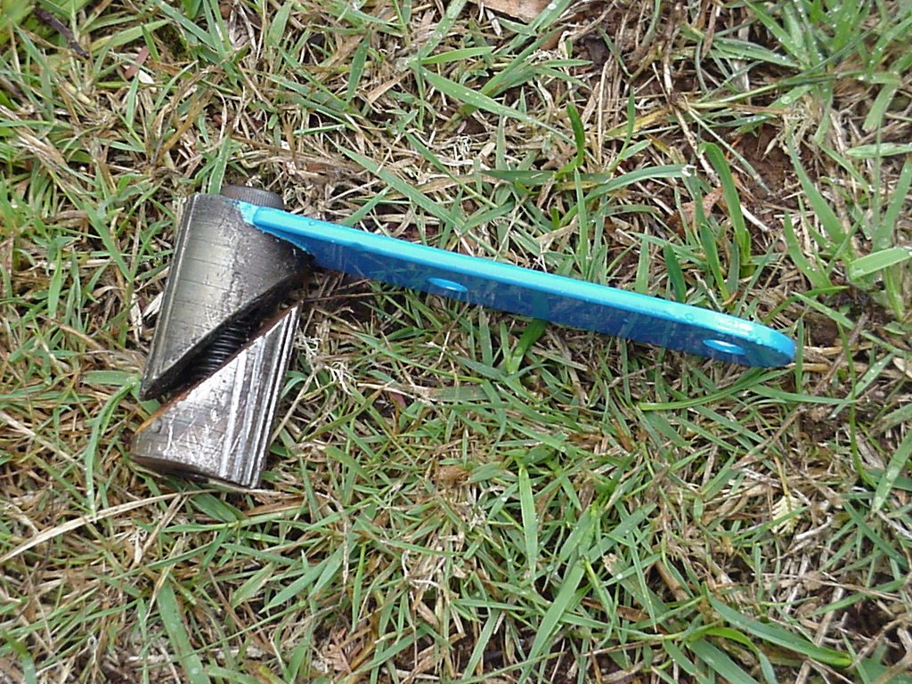
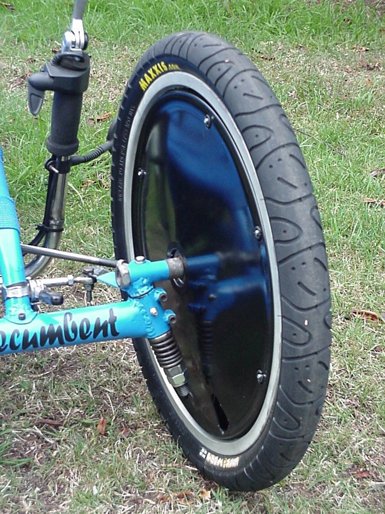
It's also well worth understanding the principals of Ackerman compensation. The difficulty I usually have is actually affixing the track arms as they have to be correctly positioned not only for height (so the track rod doesn't touch other parts of the trike) but also at the right angle. I run a string at the correct angle attempting to balance the track arm with objects before tack welding. (and I don't know any better way but this is far from ideal) Click here to download an spreadsheet specific to direct handlebars on the kingpins, Additionally to this I would say... You could also go to Peter Eland's Ackerman steering design Spreadsheet program Web page for many more. I had no way of setting the steering when I first built the trike and found my initial settings were 6% out. What a difference it made when the track rods were re-drilled to the correct angle (note in the pic the rod end is not mounted in the centre of the track arm, that being the error) as in a turn the tyres no longer sound at all like they're scrubbing. Something I'm very happy with as I am now using tyres (Maxis Hookworms) costing $25 each. Read here for trike front end adjustment information.
The track rod I used was a hydraulic line for a dirt digger being stainless steel and hollow allowing for threading inside them for the rod ends. You could also use about 10 to 12mm aluminum rod or steel rod for that matter depending on the weight saving you'd like.
Ball joints are probably best used for the steering available through bearing supply shops here in Australia. There are many different designs, some look like a scaled down version of a car steering ball joint and included a rubber dust cover (see picture 1) & others like picture 2. A cheaper work-around is to use carburetor ball joints often found on 60's and 70's cars.
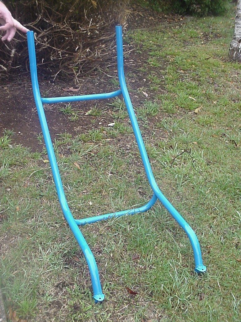
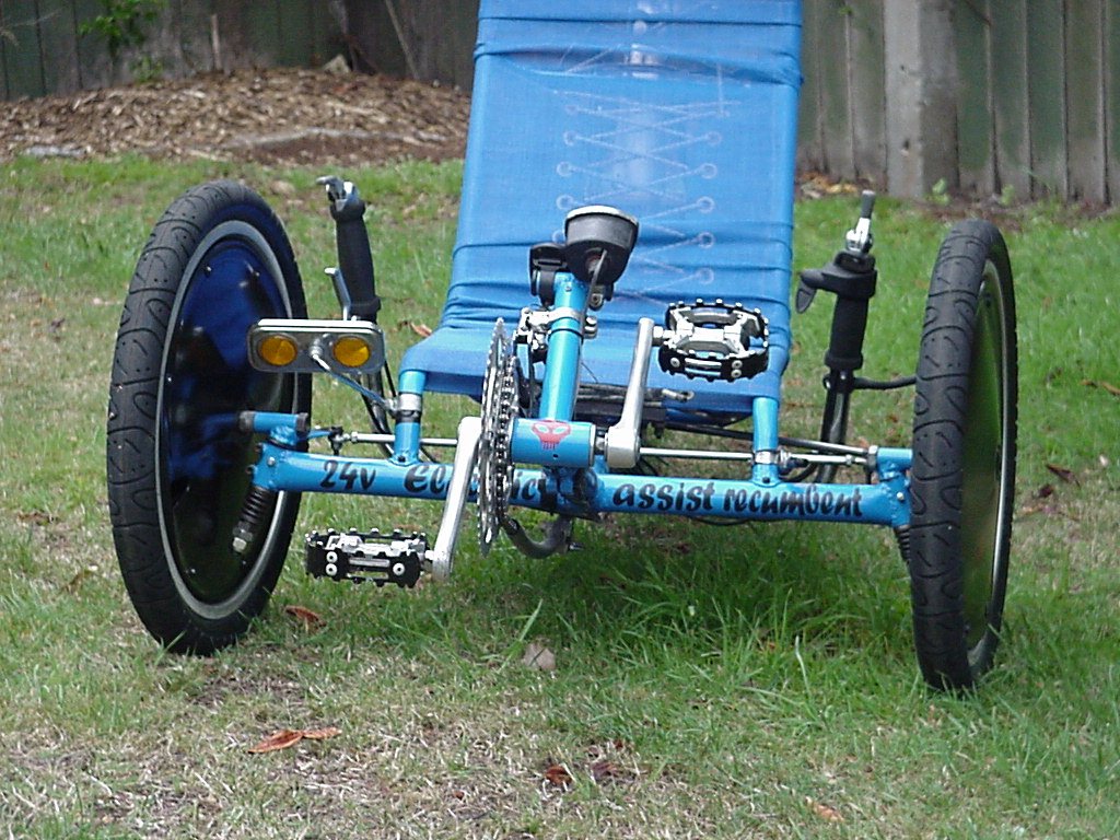
My preference is for a low bottom bracket so there is minimal clearance between ground and pedal crank. Just enough for my heel to not hit the ground. To make it rider adjustable I have a tube slide inside the boom to get the rider length right. It's hard to not damage the paint on the inside tube, especially if it's thickly coated. I had quite a strong fit before it was painted and attempted to preserve the paint by putting q clear plastic sheet over the paint work. This didn't work however as the fit was just too tight and I had in the end to grind off most of the paint to get the end of the boom in along with a liberal coating of slippery soap. Be careful using oil as my guess is it would be hard if impossible to get the boom from slipping later. (as soap dries) I haven't tried this but one way around this problem may be to have a fairly loose fit and to allow for the thickness of the plastic sheet. Accessories like cycle computers are easy to mount and cover up the open tube ends.
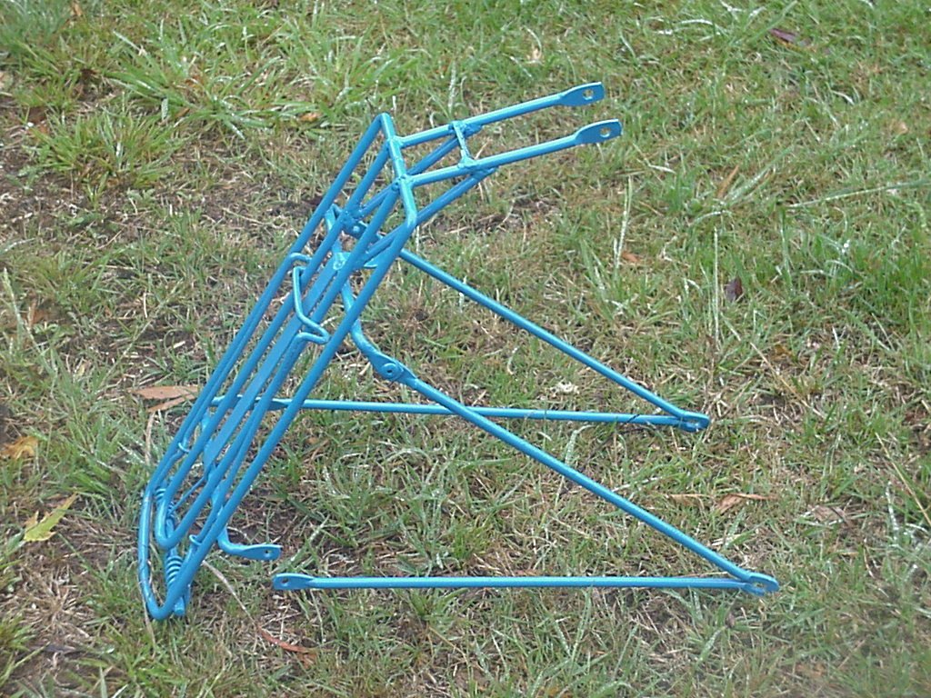
The first seat I built used aluminum tubing for a few walking frames. This didn't prove to be durable enough sadly (as it was very light and cost me $70 to get TIG welded) so I ended up opting for normal steel bike tubing. I don't have any way to bend small tubing so used the bent tubes off 6 ladies cycles. Not all ladies cycles have these sorts of bends so it can be quite a task to find matching frames with the same bends but this shows you just how many old bikes I have available to cut up. Maybe in future I'll make a tube bender. The seat bracing tubes (that connect the 2 vertical tubes) were fabricated from old chrome racing bike handlebars.
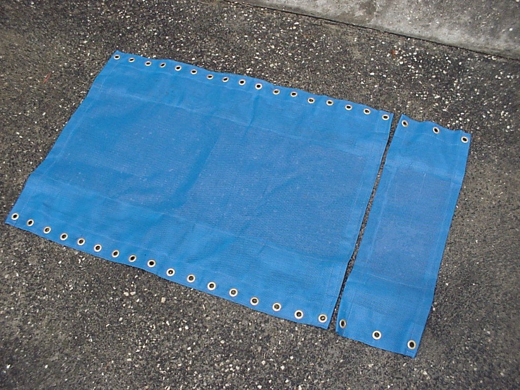
The seat mesh comes in 2 parts so I can add a detachable headrest. I haven't had a lot of experience with the lacing but am trying out elastic cord as many of the manufacturers of recumbents use. Also I found it impossible to stop the seating material bunching up in the tightest corners which is a bit of a pain. Most I see don't have the double fold on the edges so it may be that. The lower seat area has a separate cord to the back so seat tension can be controlled. Things are a bit tight with the seat coming close to the battery when the rider is in place. Here's other information for building Mesh Seats.
At present there is only one serious brake and that's on the rear which surprisingly has proved quite adequate, possibly because of the battery and motor weight placed well back. A centre pull brake is also added actuated by a friction gear lever which works admirably as a handbrake. (and could double as an emergency brake if the other cable fails at a critical time). Here are some other parking brake options. Some mount caliper brakes off the front kingpin and I went this way eventually on my Child's trike (see the new additions section) but I figured it wouldn't look so good when the handlebars aren't also on the kingpin. Maybe this would be acceptable with front mudguards, (fenders) I'm not sure but may try that one day.
The frame is powder coated blue which proves to be a very durable finish. Letter on the frame is made from black contact. (sticky on one side plastic similarly used to cover books) It takes ages to do so hope it lasts - I print out the wording onto a sheet of paper, tape the words to the plastic contact material then cut out the letters. It can be a little hard to peel the paper backing off the contact - to place on the frame tubing draw a chalk line as a base to get the letters all straight then wipe off the chalk just before placing the lettering.
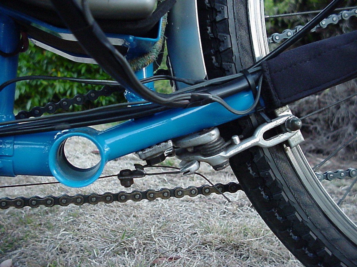
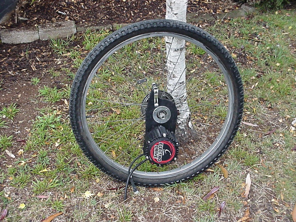
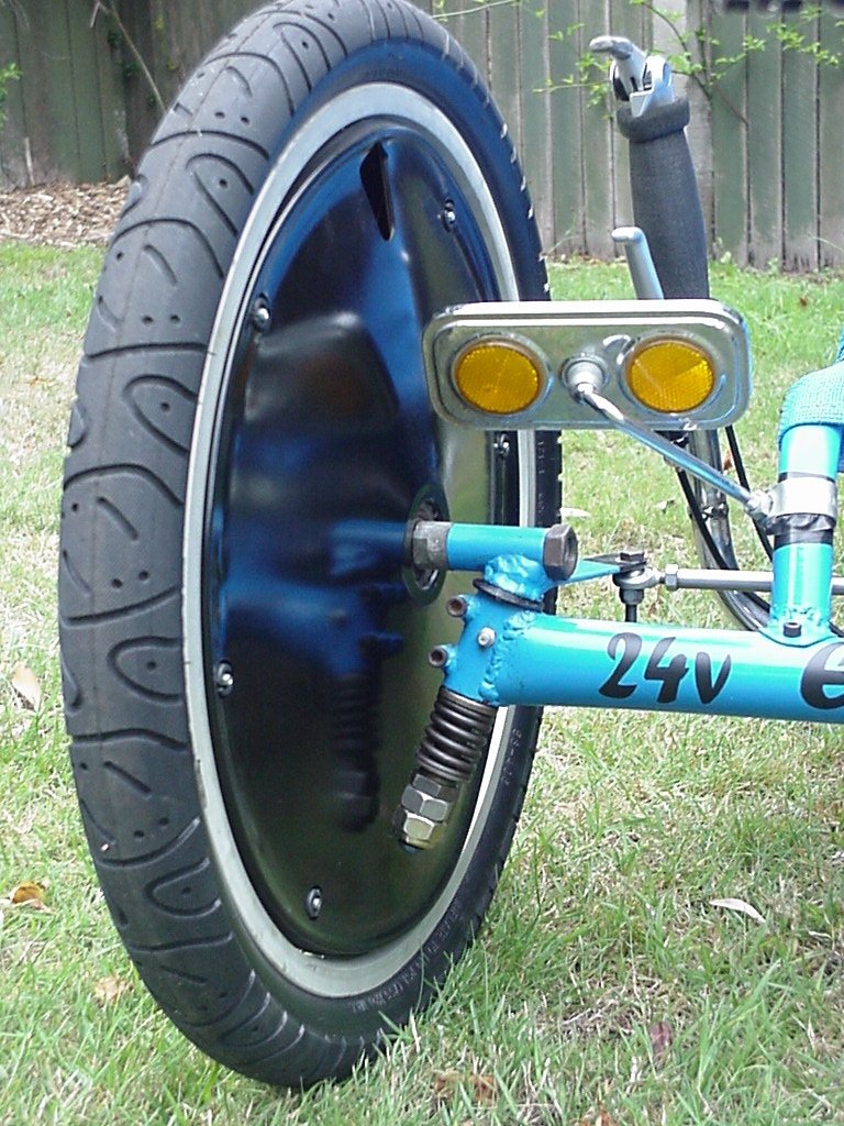
Rather than using the detachable torque arm mount supplied with the US Pro Drive kit I welded a lug to the chainstay to hold it in place. This is a critical part as any sideloads on the torque arm will swiftly damage the bearings in the motor gearbox I am told. The electric motor in the kits (as this one is) I'm told is the High torque Kollmorgen type. They can overheat/burnout if run a full throttle for extended periods, especially/mainly when the weather is very warm and there is little airflow over the motor to cool it. EG Riding slowly up a steep hill. It is strongly suggested heat transfer paste be put between the motor and gearbox to help dissipate the heat. (For more explanation of the different USPD motor types see here) Another option is to add a heat sink.
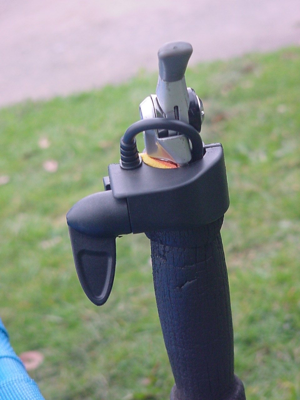
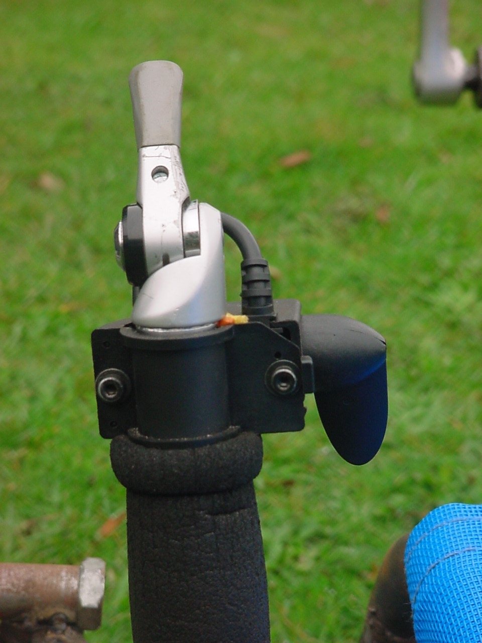
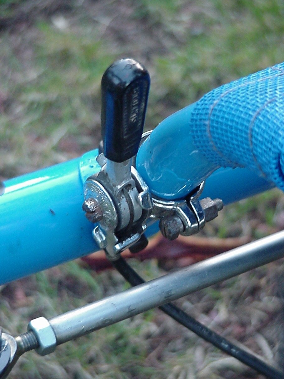
This is the new throttle handle built for a Emaxi. (Currie Australia says it's a Currie copy).
You may note that the wires are heading upward before going down
under the grip - that's because I just wasn't game to reroute the
cable in the pot because, when fitting it to the bars I broke the
lead from the pot of the first throttle and had to buy another.
It's not as comfortable as it could be as I have to place the
palm of my hand over the back and reach round pulling the lever
back with the middle finger. In the future I may move to as twist
grip lever and have a cable pull this lever on.
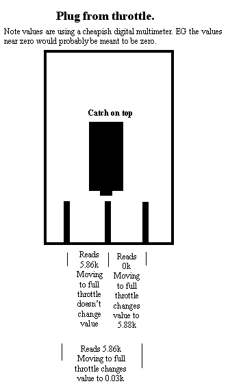
The
resistance value of the pot is approx 5k but the pot is not much
like a normal volume pot having much less sweep. Full throttle
occurs at about 40 degrees as pots bought through electronic
suppliers usually read a differing value through 270 degrees. Multimeter
reading of plug from throttle (so
you can wire your own)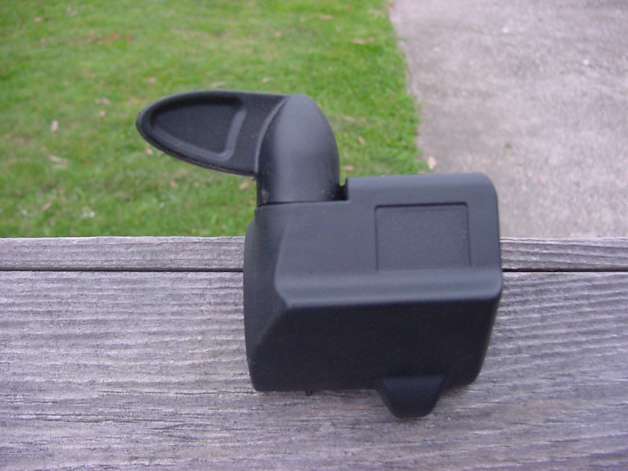
This was the throttle included in the kit. What surprised me was how much smaller the Emaxi ones are. It looks to me like they have made provision on the throttle to mount switches - I was expecting to cut this one in half but didn't have to. Scott MacGregor from www.EVdeals.com sells a Magura twist grip throttle (like a motorbike throttle) for approx $54 that would be much better than both of these. 4QD also see a twist grip throttle.
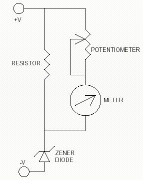
I mounted this analog voltage meter into an old mechanical bike speedo case. It has an expanded scale using basically a zener diode but I think a digital meter would be best. I expect to move to an expanded scale led or LCD voltmeter and ampmeter. Here's some links if you wanted to build your own Battery State of Charge Meter or accurate Battery Voltmeter.
A commercial volt/amp/amp hour meter is also an option but I suspect they would be close to $200 US. (it's worth anyway downloading the manual for the E meter there anyway as it has some very interesting information on batteries, discharge etc. EG It explains the Peukert exponent (and how to calculate it) that points to as you discharge a battery more quickly it's effective size decreases) One thing I love about that meter is it also calculates and displays time remaining before the battery is fully discharged. Also look at http://www.cloudelectric.com/
On the Electric Vehicle Discussion list a recent post mentions a web page with downloadable software to run a Palm Pilot from one of these meters (as they have a plug in interface) to read out the figures - interesting.
I also have a circuit that interfaces to a bike computer (where the pick up normally is) which reads amp and AH if anyone's interested.
4QD Tec Electronics Circuits Reference Archive has many circuits and other information available.
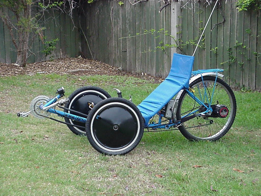
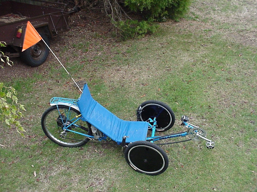
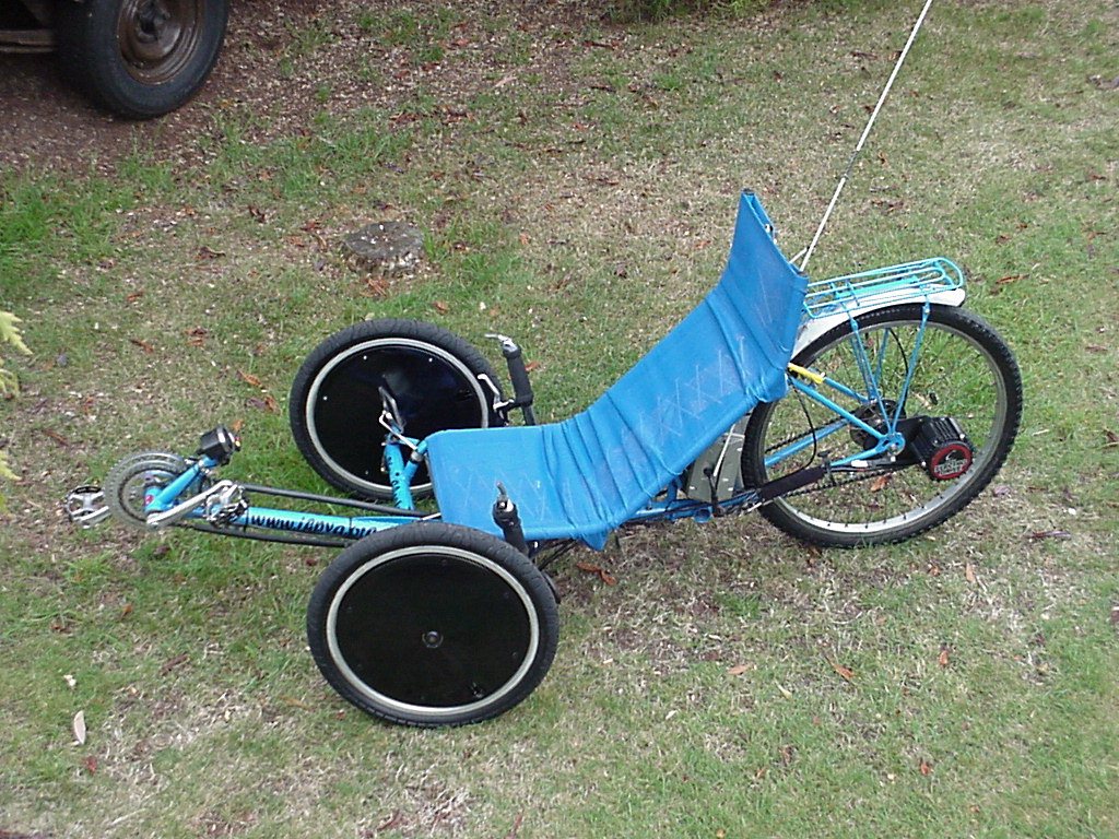
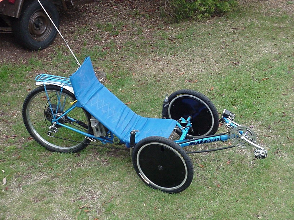
Pictures of the trike. |
|||||
|---|---|---|---|---|---|
| Top view 1 | Top view 2 | Top view 3 | Front 1 | Front 2 | Full side view |
Video's (incl sound) |
|
|---|---|
| Taking off from a stop - this is slightly uphill. - MPEG format, Viewing Size 320x200, 5 sec, file size 509k | Showing suspension movement - As you may be able to see there is a slight toe-in on compression (although the video seems to exaggerate it) but I've noticed no adverse handling affects as yet. Toe-in must be adjusted with the riders weight on the machine. MPEG format, Viewing Size 160x112, 5 sec, file size 120k |
| Traveling at full throttle but no pedaling - MPEG format, Viewing Size 160x112, 5 sec, file size 120k | Riding along - MPEG format, Viewing Size 320x200, 5sec, file size 605k |
| Showing the motor running with the back wheel off the ground. - MPEG format, Viewing Size 160x112, 5 sec, file size 120k | Showing the motor running with the back wheel off the ground. - MPEG format, Viewing Size 320x200, 5sec, file size 479k |
| Out on the road on the machine from the riders point of view (sorry for the wind noise) - MPEG format, Viewing Size 160x112, 5 sec, file size 120k | Looking/walking around the machine - MPEG format, Viewing Size 320 x 240, 14 sec, file size 1.3 meg |
The latest addition to the trike is a Recumbent human powered bike trailer.
Pictures |
|||||
|---|---|---|---|---|---|
Video's |
|||||
|---|---|---|---|---|---|
Walking round the stationary trike and trailer - MPEG format, Viewing Size 320 x 240, 9sec, file size 858k |
Riding - MPEG format, Viewing Size 320 x 240, 5sec, file size 4.8k |
Riding - MPEG format, Viewing Size 320 x 240, 4 sec, file size 400k |
Riding - MPEG format, Viewing Size 160x112, 15 sec, file size 335k |
Riding - MPEG format, Viewing Size 160x112, 7 sec, file size 175k |
|
| Wheelbase | 1055mm |
| Track (distance between the 2 front wheels) | 770mm |
| Castor | 14 degrees |
| Camber | 0 degrees |
| Ackerman/track arm angle | 62.2 degrees |
| Seat Height from ground | 290mm |
| Wheel size | Front 20" X 1.75 Back 26" X 2.125 |
| Total Length | 2000mm |
| Max Height (top of seat) | 910mm |
| Lowest Clearance (handlebar mount) | 110mm |
| Turning Circle (outside
circle measurement at full lock) Right has less turn as handlebars hit the push rod. |
Right - 7.23m Left - 5.77m |
| Front BB height from ground (to centre) | 306mm |
| Max Width | 845mm |
| Crank Length | 170mm |
| Seat Angle (inside angle) | 51 degrees |
| Front cogs (teeth) | 34 - 44 - 52 |
| Rear cogs 6 speed (teeth) | 14 - 27 |
| Gear Inch | 32 - 96 |
It's gearing ratio it is as
follows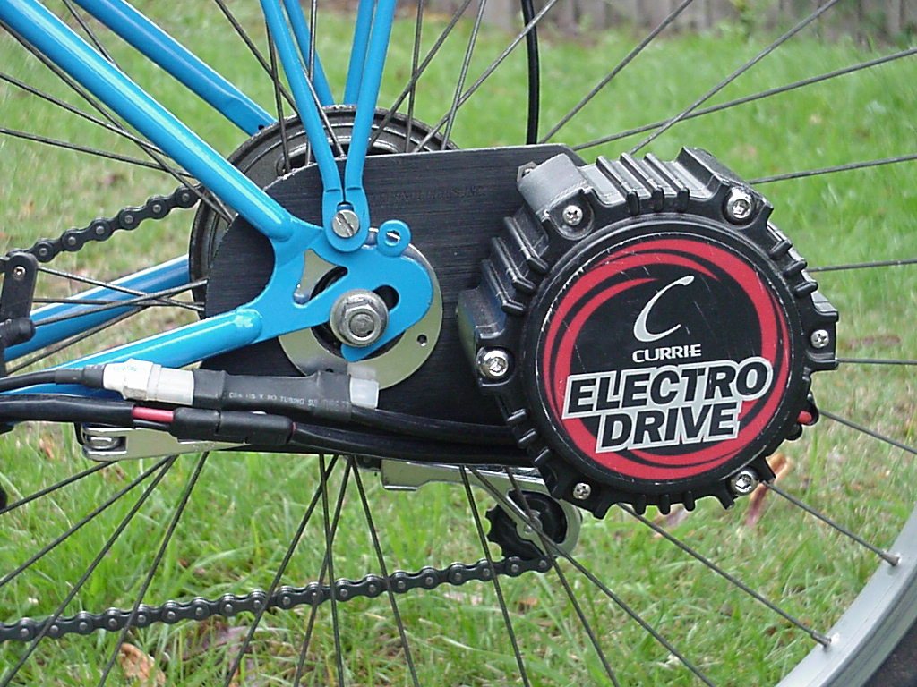
With the unit plugged in and switched on it draws 220ma at idle. (no motor activity)
With the motor off the drive unit it draws 1.3A - 1.5A with no load and at full speed.
Battery/Battery Box internal specs.
Multimeter
reading of plug from throttle. (so you can wire your own) Also from "Tim
Brown <brownt@flash.net>
There are 3 wires that go to the throttle, I call them SOURCE
(red), SENSE (brown), and GROUND (black). With ground as
reference: SOURCE is at a constant +5V, SENSE controls motor
speed. Impedance from SENSE to GROUND is about 600Kohm. SENSE is
conencted to the wiper arm of the throttle pot. When SENSE rises
above 110mV the motor control circuit energizes. Below 180mV the
motor doesn't turn but it becomes much more difficult to turn it
backwards or forwards. Above 180mV the motor starts turning. No
matter how slowly SENSE is raised the motor starts abruptly with
a slight jerk. Motor speed rises in proportion to the voltage on
SENSE until it reaches 3.6V at which point the motor abruply
jumps from medium to full speed.
US Pro drive kit Manual in Word format.
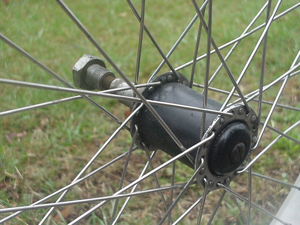
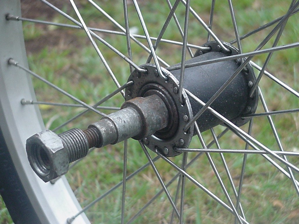
The US Pro Drive kit is different to the complete bike supplied with the electric unit too as they have a dedicated rear hub to connect up the drive to. The kit will only fit on a 36 cross 3 spoke pattern and is made for about 26" size.
It will fit on a 20" wheel but with these limitations:
Close ups of the US Pro Drive gearbox - Warning! 10 inline images all at just over 200k each, size 1280 X 960
US Pro Drive information from customers and retailers.
Cooling the motor by adding a home-made heat sink.
A list of Power Assist web pages
International Currie web site - manufacturers of the US Pro Drive.
Australian assist cycle regulations
[ Home ] [ Ally] [Stamp FAQ] [ HPV Index ] [ Design overview ] [ Bike 1] [ Bike 2] [ LWB Bike] [ SWB Trike ] [Electrified 20" Tadpole trike] [ Childs Trike ] [ SWB Trike 2 ] [ Electric Trike ] [ RWS Trike ] [Delta Trike] [Childs Hi-Wheeler] [ Bike Trailer ] [Recumbent bike trailer] [Power Trailer] [ Steering Diags ] [ Steering Mounting] [ Kingpin Diags ] [Novel HPV Ideas] [ Australian HPV Resource ] [ Links ] [Power Assist] [ Unusual Vehicles ] [ Electric RC Models ] [ EV Circuit Diags ] [Tas HPV] [QLD PP] [Qld HPV] [Skycycle] [Bleriot] [Building HPV's] [Darryl] [Null Modem] [ Pedalezy ] [ USPD ] [Zeta] [Power Attachment] [Email]
Friday, January 30, 2009