This project has been for me the most challenging of all. Not only because a greater proportion of the frame has to be fabricated but also the RWS system is very hard to design to be fully functional at speed. After making 4 tadpole style trikes I wanted to try something a little different but was not prepared for the complexity of this design. When researching the RWS concept several people replied and were not so favourable about it working successfully.
It is possible to have a
rear steer tricycle that is stable. but they
must have as long a wheelbase as possible,
85% of the weight on the front wheels and be as low as possible.
We raced one for a couple of years until we realised that NO
three wheeler can keep up with racing two-wheelers. As a street
machine the trike is impractical because it takes up too much
road space and is tool low to be safe.
Sorry to rain on your
party, but I think you'll have a lemon!
But the Tricumbent Raven is a sort-of-rear
steer trike.
.
Although it is possible put your work
into a project that is worthy of
the work.
To some degree they are right and so with this project I would say approach it with a bit of caution. I am not game to go faster than 25 k/hr because of the feel when at speed. Sharp steering movements throws your weight with the turn and upsets the stability of the trike. Also I have found the steering movement takes a little getting used to and I tend to move it in the opposite way that's needed when faced with a quick steering decision. Also when an obstacle (say another trike) is passed, I tend to push the bars away from it to have clearance for my hands on the bars and with this design this make the trike steer into the object.
Now that I have got all of the negatives out into the open, are you still interested? If so read on as there are also some great pluses. As with all of the HPV's I tackled so far the aim was to build it using material that was readily available and cheap to buy. I have a heap of old bike parts and so wanted to use these as much as possible, at least until the machine proves to be functional. All of the welding is done with a MIG and I have little idea of what other methods one can use. Overall the cost to me was about $50 as I had to buy only limited new material and bike parts. Refer to Recumbent Cycle Component Design & Construction page.
 There are really only 2 main parts to the whole
frame being the main body and the seat.
There are really only 2 main parts to the whole
frame being the main body and the seat.
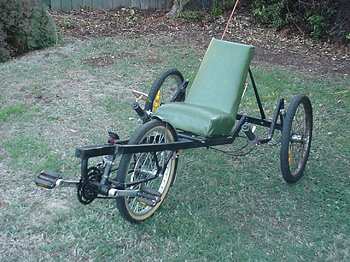
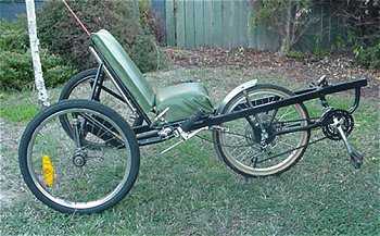
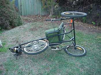
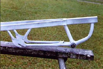
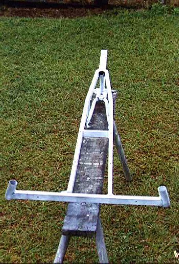
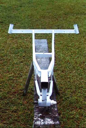
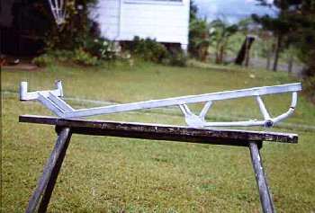
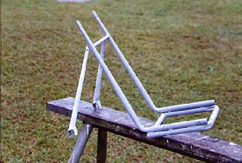
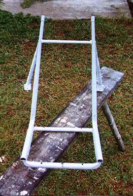
I first started by bending and then tack welding the rectangular tubing for the frame. The rear part of a 20" bike frame is needed for the front section and is then cut and tack welded to the rectangular tubing. It is best to have the front wheel in place to be certain of the correct spacing as this will weld up to be quite strong and is hard to correct later. Extra tubing is added near to the wheel bolting position for strength. I cut a slit in the end which passes over the rear part of the fork so there is more area to hold. see picture1 & picture 2 & picture 3 & picture 4 & picture 5 & diagram 1 & diagram 2.
After all of this is tack welded assemble it all and you will have some idea how the trike will look. I spent a lot of time fiddling with the angle the frame makes at the rear to get the center of gravity as low as possible and this still could do with being a little lower.
This has the same arrangement as the tadpole
style trike so refer to the article as well as diagram 1 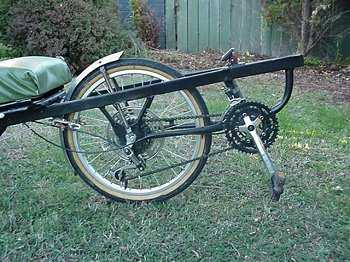 & diagram 2. I have purposely not made very
much steering movement so the trike will be safer to ride. Even
with this amount it will lift a wheel at 20 k/hr if steered
sharply. The lack of movement makes it a bit of a pain for
manoeuvring but normal riding is not affected in any way. In
terms of setting up the steering geometry the best information I
have found says that the setup is all the same as front wheel
steering but usually needs to be more finely tuned. Refer to this
article for trike steering design. The control rod needs to
run through 2 tubes welded onto the rectangular frame to give
support and stop it's flex. (see picture)
I used this type of ball joint which was
around $14 but this one is a little more
protected from dirt and cheaper at about $9.
& diagram 2. I have purposely not made very
much steering movement so the trike will be safer to ride. Even
with this amount it will lift a wheel at 20 k/hr if steered
sharply. The lack of movement makes it a bit of a pain for
manoeuvring but normal riding is not affected in any way. In
terms of setting up the steering geometry the best information I
have found says that the setup is all the same as front wheel
steering but usually needs to be more finely tuned. Refer to this
article for trike steering design. The control rod needs to
run through 2 tubes welded onto the rectangular frame to give
support and stop it's flex. (see picture)
I used this type of ball joint which was
around $14 but this one is a little more
protected from dirt and cheaper at about $9.
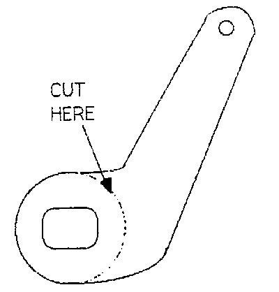
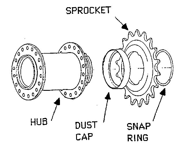
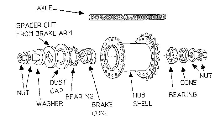
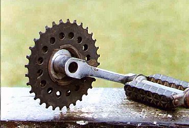
I have used rear coaster wheels for the 2 rear wheels as they have a larger axle than most normal bike front wheels. I've noticed that the 'free style' bikes especially have these larger axles on the front which would do fine and may look slightly better if you can find them. An added bonus with these is they often have more than a normal amount of spokes as well as a thicker spoke which helps with the sideloads a trike puts on the wheels. So if using the coaster wheels first prepare the wheels in this way. Grind down the torque arm so that it can act as a washer. Referring to the sprocket diagram remove the sprocket and either grind it down so that it acts as a washer to hold the dust cap on or find a second snap ring to replace it. The front axle is a hardened steel bolt replacing the normal axle and can be purchased from the local hardware store for about $2 each. There are different grades of hardened bolts. As I understand it you can 'read' the grade by counting the scribes on the bolt end. The scale is up to 10 (being the hardest) and 2 marks are subtracted from the total count. I use ones marked with 3 scribes which is still quite mild but they haven't bent yet. I'm told not to go too hard as they will be very strong in tensile(stretching) strength but also brittle so could sheer in use.( I've tried normal axles and some do bend.) Referring to the diagram the inside cone (cog side) is drilled out. This isn’t as easy as it is to say as the nut is hardened an wore a drill quickly. The following will sound very crude but it does work. I wait until the drill and nut gets red hot before pushing it through. If you wait like this it is easy work but will pretty well destroy the drill bit. It doesn't really matter if the nut is damaged slightly as on that side there is another set of bearings so it doesn't matter if it doesn't spin freely. All of the original nuts, hub insides and axle are discarded and a nylock nut is used on the outside of the wheel. The bolt axle then passes through the (as per the diagram) right drilled out cone nut, bearing, hub and then screws into the brake cone with the nylock nut holding the ground down torque arm against the brake cone. The nylock nut is needed at least on the left side as the torque arm nut will tend to unscrew with the forward motion.
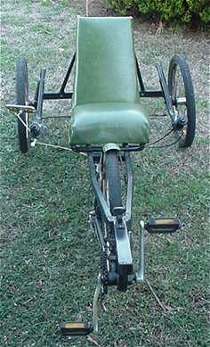
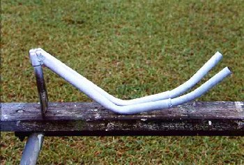
The handlebars are made by extending the goose-necks from a normal bike. see picture and diagram. I fiddled around with several bends of the bars to get some sort of pleasing lines but didn't find this at all easy. Cut the extension from the goose-neck and grind it smooth. Tubing of the correct diameter is shaped to fit and welded. Another option would be to turn the goose-neck to the side and bolt the bars as per a normal bike. There is a bit of stress at this point, especially if you rest your arms on the bars whilst riding.
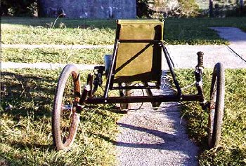
 Seat
SeatA kitchen chair frame was used as the basis for the frame. It was remodelled a little for shape and 2 rear supports were added. The seat was bolted to the frame by welding nuts into the frame which were set flush with the top of the tube.
See picture 1 & picture 2 & diagram. The seat base is 5 ply with foam as the filler and vinyl bought from an upholsterer and stapled onto the ply.
So how does it ride? Keeping a steady pace around
the bike paths I found it to be quite enjoyable. There is
something about the pedal angle that makes it easier to pedal or
gives more power in the pedal stroke than the tadpole trikes I
built. In fact this is really only set up at the moment with 5
gears and this seems fine which wasn't the case for me with
other. There is a bit of getting used to the steering system as
it appears to be in reverse to what I expect. It may be that I
expect to move them up and down opposite to one another, I'm not
sure. A front mudguard was added to stop road waste being flicked
up on the rider. A rear guard may fit ok and give better
coverage. An extra piece of rectangular tubing was 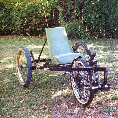 added for the
mount which also doubles as the front brake caliper mount.
Without drum brakes on the rear and of course no forks there is
no place to mount brakes but I find the front one quite adequate.
The gear and brake cables need to be thought through for length
as there is a lot of steering movement and there needs to be
considerable slack for free movement. The area behind the seat is
great for carrying gear as it can slip in down low onto the main
frame.
added for the
mount which also doubles as the front brake caliper mount.
Without drum brakes on the rear and of course no forks there is
no place to mount brakes but I find the front one quite adequate.
The gear and brake cables need to be thought through for length
as there is a lot of steering movement and there needs to be
considerable slack for free movement. The area behind the seat is
great for carrying gear as it can slip in down low onto the main
frame.
The front derailleur posed a bit of a problem for
me. I found it hard to get enough tube length so that it didn't
hit the top as the longer this tube the lower the pedals are to
the ground. This left me with only just enough room for mounting.
Because the trike will only be ridden at a slow speed I have now
moved to 3 small cogs on the front similar to what is on the child's trike. This makes the gearing
range cover the range of speed I intend to go being from 0 to
about 25 k/hr. see picture 1 & picture .This now leaves more than enough
room to mount the derailleur but if you go this way don't do what
I did and mount the largest cog too close to the pedal arm. The
problem here is the front derailleur can't reach across enough to
engage the biggest cog and can also hit the crank. A lot of this
is trial and error and the problem was fixed quite easily by
turning round the axle as the other side is a little shorter.
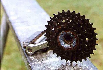
Some cassettes have the cogs joined and others have them slide
onto a spline with spacers in between. If you are 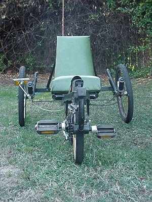 needing to remove a few of these on the
spline type there isn't anything to hold them together as they
rely on a nut which will need to be ground off. You will have to
tack weld the last cog to the body although this doesn't pose a
problem (as long as you don't melt the plastic spacer) as it only
needs a small amount of weld because the spline does the work
under load. If you ask at bike shops they often will give you 2nd
hand parts like cassettes (that's where I got my 2 from) if it
means they will only throw them away I am toying with the idea of
making the steering deliberately self centering. Maybe by adding
springs or rubber bands to the control rod to exhert a pull to
center, not unlike the setup of the stick on a Radio Control
set.. The steering movement would then be against the springs and
this should be fine as long as they aren't adjusted too tight.
I've noticed that leaning into the turn has made a big difference
to the feel of handling but this doesn't help in unexpected
manoeuvres and am hoping the self centering will at least get the
trike straight if one can trust it and let the bars center.
Failing that maybe using a steering damper used on some motor
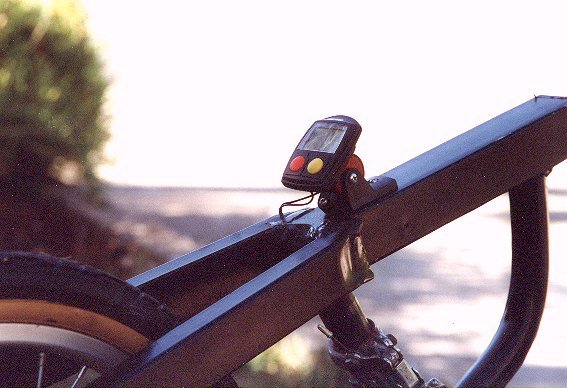
bikes may help. Recently added is an
electronic bike speed sensor.
needing to remove a few of these on the
spline type there isn't anything to hold them together as they
rely on a nut which will need to be ground off. You will have to
tack weld the last cog to the body although this doesn't pose a
problem (as long as you don't melt the plastic spacer) as it only
needs a small amount of weld because the spline does the work
under load. If you ask at bike shops they often will give you 2nd
hand parts like cassettes (that's where I got my 2 from) if it
means they will only throw them away I am toying with the idea of
making the steering deliberately self centering. Maybe by adding
springs or rubber bands to the control rod to exhert a pull to
center, not unlike the setup of the stick on a Radio Control
set.. The steering movement would then be against the springs and
this should be fine as long as they aren't adjusted too tight.
I've noticed that leaning into the turn has made a big difference
to the feel of handling but this doesn't help in unexpected
manoeuvres and am hoping the self centering will at least get the
trike straight if one can trust it and let the bars center.
Failing that maybe using a steering damper used on some motor
bikes may help. Recently added is an
electronic bike speed sensor.
One modification I will make soon is to remove the lower metal part of the seat frame. It isn't needed and raises the centre of gravity just that extra bit (which isn't a good thing). This would mean mounting the seat base to the main frame and modifying the back frame to mount independently. It did surprise me how heavy the seat assembly is when I recently removed it and can see why the weave seat material is used in a lot of HPV's. Want to see other Rear Wheel Steering Cycles information?
| 10 sec MPEG video viewing size 160 x 112, 232k | 15 sec MPEG video viewing size 160 x 112, 344k | 15 sec MPEG video viewing size 160 x 112, 344k |
| Wheelbase: | 840 mm |
| Track: | 830 mm |
| Seat Height: | 400 mm |
| Wheel size: | 20" x 1.75 all round |
| Total Length: | 1630 mm |
| Max Height: | 740 mm |
| Total Width | 920 mm |
| Lowest Point: | 195 mm |
| Turning Circle: | 6.4 m |
| Gears: | 15 speed, derailleur |
| Kingpin Inclination: | 14 degrees |
| Castor: | 10 degrees |
| Camber: | 0 degrees |
| Pedal height above ground | 130 mm |
| Crank Length | 165 mm |
| Front BB Height to Center | 295 mm |
| Seat Angle | 110 degrees |
| Weight (approx) | 25 kg, 50 pounds |
| Weight Distribution | 79 % rear, 21 % front |
| Front Cogs (No of teeth) | 21-24-28 |
| Rear Cogs (No of teeth) | 14-17-20-24-28 |
| Gear Inch Range | 15-40 |
:
[ Home ] [ Ally] [Stamp FAQ] [ HPV Index ] [ Design overview ] [ Bike 1] [ Bike 2] [ LWB Bike] [ SWB Trike ] [Electrified 20" Tadpole trike] [ Childs Trike ] [ SWB Trike 2 ] [ Electric Trike ] [ RWS Trike ] [Delta Trike] [Childs Hi-Wheeler] [ Bike Trailer ] [Recumbent bike trailer] [Power Trailer] [ Steering Diags ] [ Steering Mounting] [ Kingpin Diags ] [Novel HPV Ideas] [ Australian HPV Resource ] [ Links ] [Power Assist] [ Unusual Vehicles ] [ Electric RC Models ] [ EV Circuit Diags ] [Tas HPV] [QLD PP] [Qld HPV] [Skycycle] [Bleriot] [Building HPV's] [Darryl] [Null Modem] [ Pedalezy ] [ USPD ] [Zeta] [Power Attachment] [Email]
Last updated Friday, 30 January 2009