Version 1.0
Written By Rickey M. Horwitz
The material contained in this section is protected by U.S. copyright laws. Any unauthorized duplication or publication of the material contained in this section is prohibited by law.
I don't have the resources to go into great lengths on how to weld. If you don't know how to weld, then you better learn quickly. I have provided this summary on welding so that you can determine which technique best suits your skills and resources.
There are four basic methods of bonding a metal frame material together. These methods are as follows:
Please do not critique or correct me for omitting other processes such glue bonding or some other lesser-known bonding method that has no place in MY discussion.
Oxyacetylene
The most common form of welding is oxyacetylene. This method is good for welding high carbon steel only. Almost every shop has an oxyacetylene torch. If you have access to an oxyacetylene torch, use it!
Brazing
Brazing is accomplished by using a bronze alloy that is melted and adhered to the parent metal. Normally the melting process is performed using an oxyacetylene torch. However, MAP gas can be utilized, but is not quite hot enough to do most work involving thick parent metals. It is best to use a low fuming bronze rod and applicable flux. Brazing can be used for both CroMo and high carbon steel. Best of all, brazing is a preferred method for attaching small frame components such as cantilever posts and cable stops.
Although some frame builders claim that a TIG welded frame is stronger than a fillet brazed frame (the filler bronze doesn't have the strength of CroMo), a brazed frame does not require a post heat treatment. This is because the brazing process does not require as much heat, hence the parent metal is not affected.
If you are a novice, brazing is strongly preferred as it produces good results. However, good results require that all joints are mitered to close tolerances as to provide a uniform fit. This practice makes the brazing process much easier and predictable.
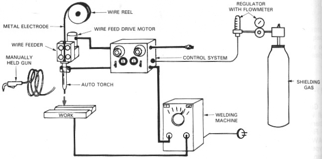
MIG
MIG can weld aluminum, carbon steel and CroMo. A MIG welding machine is generally inexpensive and is readily available at most school metal shops. For the Thunderbolt project, a 100 amp MIG would need to be employed. Contrary to what anyone has heard, MIG welding does not produce good quality welds. MIG welding is popular for applications requiring lower heat or for automated production. The welds are generally sloppy, but effective. The cheapest bikes built today use MIG welding as these manufacturers have no pride in their workmanship. MIG welded CroMo frames require a post heat treatment just as a TIG process requires. Although I speak of this process in a disparagingly manner, I strongly endorse its use for the hobbyist as it is the cheapest way to start welding.
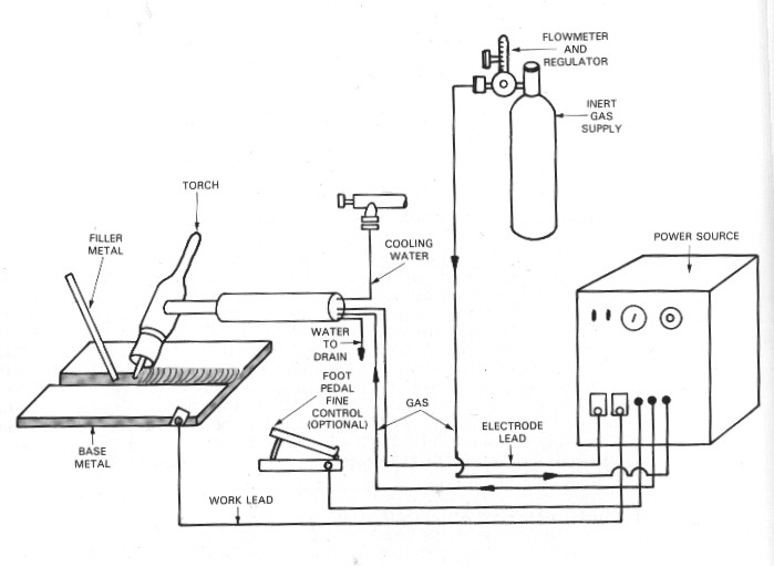
TIG
As with MIG, TIG can weld just about anything that can be welded. TIG welding is the most superior method for all three materials reviewed in chapter 1. Additionally, TIG is the only reliable method for welding aluminum. However, a TIG welder is more expensive than both MIG or oxyacetylene torches. A basic TIG unit costs around $1500. Even at this price, the owner must invest in further options to weld thin wall steel as most cheap TIG welders are unable to weld DC at 30 amps or less. Also note that the TIG method requires greater skill and patience. Although a preferred process, I do not suggest investing in such an apparatus unless you are dead serious about frame building.
CLOSING
Although this section appears vague, I am only presenting available options. If you desire, a combination of two or more of the welding technologies can be used. It's up to you.
or the latest changes, look at What's New
This section takes over 2 minutes to download at 28.8K (2 min. 12 sec.)
Notice
The material contained in this section is protected by U.S. copyright laws. Any unauthorized duplication or publication of the material contained in this section is prohibited by law.
Caution The written material contained in this section is protected by U.S. copyright laws. Any unauthorized duplication or publication of the material contained in this section is prohibited by law.
Introduction
This chapter focuses on the basics of recumbent tricycle designs. In order to keep the concept elementary I have simplified many of the terms and explain the technology in detail at a level that most people will enjoy. If the explanations contained in this document do not address your concerns or doesn't present the 'big picture', please email me (Rick) at rhorwitz@flash.net.
Tadpole vs. Delta Design
Before elaborating on the design overview, I thought it would be appropriate to offer some reasons why I prefer the two wheels front, one wheel aft design commonly referred to as the 'Tadpole' configuration. The most common tricycle design is the single wheel in front, two-wheel aft configuration (1F2R) referred to as the 'Delta' design. Although this design has many merits such as reduced cost, weight and complexity, it has one outstanding drawback -- handling. Although a well-designed Delta configuration offers good handling, the basic geometry prevents the vehicle from exhibiting excellent handling qualities as compared to a tadpole configuration (2F1R). Having limited experience with Delta trike designs, I rely on articles comparing both configurations. In these publications the tadpole comes out ahead as the preferred design for all-out handling. In summary, these articles claim that delta trikes tend to over-steer making a minute twitch at the handle into an exaggerated steer. Personally, the only recumbent delta I have ridden had more of a tendency to under steer as the front wheel had little weight to make it effective. As for a comparison, most people agree that the handling characteristics of a tadpole configuration is slightly more forgiving and predictable than the delta.
A tadpole configuration uses the same steering geometry design principles as an automobile. Geometry considerations such as Caster, Camber, and Toe-End exist for this trike design just as they do on an automobile. In contrast, a Delta design uses geometry similar to that of a bicycle. The design objective for the Thunderbolt was to create a 'Cycle-Car', not a bicycle with a third wheel.
Front Steering vs. Rear Steering
One gimmick that pops up every year or so is a rear steering HPV. The rear steering concept has been applied to both Tadpole and Delta trike configurations without any staying success. Although the virtues of rear wheel steering include a simplistic design, lighter weight and a smaller turning radius, the fact that the trike drives like a forklift makes it a losing proposition every time. Since people have a fascination with gimmicks, the rear steering trike shall always have a place in the HPV industry.
Lean Steering Trikes
A lean steering trike is a three wheeled vehicle that steers by virtue of leaning the rider's body into the desired direction of the turn. Although several variations exist, the most notable implementation is where the seat moves in relation to the frame causing the vehicle wheels to turn. A stationary horn or tiller is fixed to the frame (this can also be a U-bar) allowing the rider to lean the seat left or right, hence steering the vehicle. Since the rider leans into the direction of the turn, the center of gravity is optimized producing a trike with excellent low speed handling. The concept is similar to steering a bicycle with one obvious exception: the leaning is linear to the steering and not by the G forces applied. Consequently, the steering in this implementation is not optimized for higher speeds. Obviously, the example explained here may not be characteristic with all lean steering tricycles.
Lately, there have been other implementations of the lean steer trike that allow the front wheels to lean into the direction of the turn. Not only does this enhance the handling characteristics of the trike, it also relieves the wheels from side-loading allowing larger diameter wheels. As with most emerging technology this concept is relatively new, requiring future improvements to make it practical.
The main premise of a trike is to provide a stable platform that does not require balancing. Although lean steering has the potential of optimized handling at lower speeds, it does require equilibrium to master. As with rear steering, this is yet another gimmick that comes and goes. Those who are hopelessly hooked on two wheels will be glad to know that there will always be a lean steering trike in at least one incarnation or another.
Front Wheel Drive vs. Rear Wheel Drive
One of the virtues of the recumbent industry is the ever-evolving, innovative change being made. The recumbent trike market is undergoing even more changes. The recent technology making news is front wheel drive systems. The main virtue of a front wheel drive system is superior traction and a localized drive train. Currently, two trike manufacturers build front wheel drive, tadpole-configured recumbent tricycles. This technology is still in its infancy as both manufacturers have several problems to address. Two outstanding problems preventing this technology from instant success are weight and reliability considerations. Ironically, one would think that a localized drivetrain would have these points as virtues instead of liabilities. Perhaps in the near future, these problems shall be worked out, making it a desirable alternative to the conventional, long-chain and idlers of the rear drive system.
Suspended Trikes
A well-designed suspension system can offer a featherbed ride regardless of the conditions of the road. Up until recently, most implementations have been limited to front suspension, as a majority of the rider's weight is placed directly over the front wheels. However, a lightly dampened front suspension system hampers handling, as the trike is more inclined to sway. More sophisticated suspension designs use a parallelogram configuration that reduces sway and brake dive. Simplistic designs avoid these side-effects by restricting the shock travel to under 25 mm (1 inch).
Since rear suspension poses no severe adverse consideration to handling or steering geometry, it is gaining fast popularity. With easy-to-route chain management systems, and the cranks being so far forward from the swing arm, it's obvious to see that rear suspension can be easily adopted to a tadpole-configured recumbent trike with little compromise. However, the virtue of a rear suspension system is refutable as the rear wheel delivers less than 1/3 of the total shock felt by the rider. Secondly, the swing arm designs currently employed on these trikes are all more susceptible to side-loading forces than conventional triangulated rear ends.
Basic Trike Frame Design
In this section, I discuss the basic elements of a Tadpole trike design. I also attempt to discuss the hierarchy of each as they apply, so that the readers can understand that any trike design is actually a compromise of all of these elements.
Weight Distribution
The weight distribution of a trike dictates how well it handles. The more weight on the forward wheels, the better the cornering. However, too much weight on the front wheel causes the rear wheel to be too light, and the rear wheel to either wash-out during hard cornering or to end-over during braking. Too much weight in the rear of the trike causes it to capsize even during mild handling as the single wheel has the majority of weight. A trike with 70/30-weight distribution is optimum.
Center of Gravity
Forget what I said about weight distribution. If all the weight is placed well below the axle, the trike is going to have excellent handling regardless of weight distribution. Obviously, a low slung vehicle does have several disadvantages including visibility, safety and comfort.
Wheelbase
The effect of the wheelbase on a trike influences the steering, weight distribution and overall comfort. The wheelbase is the length between the rear wheel axle and front wheel(s) axle. A short wheelbase makes the turning radius of a trike much smaller while a long wheelbase makes the turning circle larger. Additionally, a trike with a short wheelbase exhibits faster steering than a trike with a long wheelbase. A short wheelbase trike generally places more of the payload weight on the front wheels. On the other hand, a longer wheelbase trike offers a much smoother ride, as the rider is not placed on top of the wheels. Obviously, a happy medium is needed. For the Thunderbolt and Zephyr, I used a 43-inch wheelbase. If all-out performance is required, a much smaller wheelbase should be used.
Wheel Track
The wheel track is the width between the two front wheels. The wider the wheel track the less susceptible the vehicle is to capsizing during cornering. However, if too wide, the vehicle becomes impractical on most bike lanes. A 32-inch wheel track offers excellent handling and is practical for all bike roads, too.
Steering Geometry
The quality of the steering system and steering geometry also dictates the performance of the trike. The steering geometry is outlined later in this chapter.
Frame Design
The last element in basic trike is the frame design. There are several issues here that affect efficiency and handling. The most important issues of the frame is weight and rigidity. Along with rigidity comes stability, as the lack of frame or wheel flex is always desirable. Beyond these basic requirements are other elements that should be equally noted. Reliability, cost, ergonomic and convenience are but a few requirements that the designer must consider.
An excellent frame configuration is a 3-dimensional space frame (e.g., Greenspeed/Zephyr/Diablo), as it is both extremely strong and lightweight. The next choice is a web-gusset, reinforced frame (e.g., Thunderbolt/Spitfire), as it is strong, relatively light and compact. However, the lowest weight, lowest cost, and least rigid of any vehicle would be a two-dimensional frame without seat stays (e.g., Terra Trike and older Trice).
Summary
The success of a recumbent tricycle design is a careful mixture of Weight Distribution, Low Center-of-Gravity, Wheelbase, Wheel-Track, Steering geometry and frame configuration.
A recumbent trike frame is only as good as the steering, as it behaves similar to an automobile. Therefore, the steering system is inherently complicated as more than a single geometry is used to define it. In this section, I'll discuss the fine art of steering geometry.
Caster Angle
The first geometry is the caster angle. This angle is the kingpin plane relationship to the wheel contacting the road (contact patch). Refer to the drawing below. As the drawing illustrates, the kingpin points down in front of the tire's contact patch. This relationship between the contact patch and the kingpin forces the wheels to point inward as weight is placed on the wheels. Increase the kingpin angle, and more force is applied to bring the wheel inward. The resulting effect forces the steering system to return back to a neutral (or straight) position. We use a 12° caster on the Thunderbolt project. As a footnote, a standard automobile uses a 4-5° caster and a race car or go-cart gets much steeper.
CamberThe next geometry is the camber angle of the front wheels. If the wheels are at exact right angles to the ground (90 degrees) or the distance between the top of both wheels equals the distance between the bottom of both wheels, the camber is said to be neutral. If the distance between the top of both wheels is shorter than the bottom, the camber is said to be negative. And, if the distance between the top of both wheels is longer than the bottom, the camber is said to be positive. Normally, a negative or neutral camber is desirable. The Thunderbolt project has adjustable camber so that you can adjust it to your satisfaction.
Toe-EndThe toe-end is actually the desired relationship of the front wheels. Each wheel points inward very slightly when the vehicle is pointed straight. On a trailing arm steering system (such as the Thunderbolt), both wheels have a natural tendency to point inward, as the castering effect forces them to do so. However, the forward motion of the wheels counteracts this force. To reduce this effect, we bring-in, or toe-in, the front wheels slightly. A toe-end of no more than 0.1" is sufficient.
Ackerman Steering CompensationThe Ackerman steering compensation provides a way for a vehicle to turn without the front wheels scrubbing. In layman's terms, this means that when the vehicle is steered in either direction, the inside wheel shall always turn sharper than the outside wheel. Let's look at this with an example: My Thunderbolt can turn around a 15-ft. circle. This means that the outer tire is pointing at a particular angle that follows the 15-ft. circle. However, the inside wheel, which tracks 32 inches closer to the inside, must turn at a sharper angle so that it can follow a 9.5 ft circle. Obviously, if both wheels turned at the exact angle, they would scrub when the vehicle turns. Not only would this wear out the tires, it would also cause the vehicle to drastically slow-down during cornering.
Although Ackerman steering compensation is a requirement, it can make the steering sensitive, leading to over-steering at high speeds. As a way to make the steering less sensitive, an Anti-Ackerman is used. An Anti-Ackerman is actually a partially compensated Arckerman implementation and allows a small amount of scrubbing when turning. Although this Anti-Ackerman slows the vehicles into corners, it does allow the trike to sustain faster speeds without steering instability. My personal T'bolt can sustain speeds greater than 50 MPH without steering instability, as it uses a 2° Anti-Ackerman offset.Kingpin Inclination (Center Point Steering)
The inclination of the Kingpin allows the steering axis to turn precisely on the center patch of tire contacting the pavement (hence the name Center Point Steering). Because the steering axis rotates directly over the contacted patch of tire, the steering is less affected by defects in the road, hence reducing 'bump steering.' In addition this concept also reduces brake pull. Another by-product of kingpin inclination and Caster allows the camber to change in relationship to the wheel steering angle. This compensation allows the wheels to lean into the corner in which they are turning. Ultimately, this dynamic orientation modifies the wheel geometry resulting in enhanced handling. The kingpin inclination is at a 90-degree plane in relationship to the caster angle.
Some manufacturers refuse to implement center point (pointe for you over the pond) steering into theirs designs. In some cases the designer has placed the King Pin axis so close to the wheel that the king pin centerline becomes very close to the tire patch. However, in most cases the designers or builders are just plain ignorant, as their designs completely ignore this concept.
Kingpin to Wheel Axle OrientationThe placement of the wheel axle, in relationship to the kingpin, drastically affects the steering. If the wheel axles are placed in front (lead) of the kingpin axles, the 'caster effect' is defeated making the steering unpredictable. However, if the wheel axles trail too far behind the kingpin, the steering may be influenced by road shock and by braking. Again, this occurrence is referred to as bump steering and brake pull. Ultimately, the wheel axle and kingpin should intersect or be within 0.5 inches trailing.
Note In this section, I address the stay reinforcement issue by referring to a Seat Tube. The name originates from descriptions intended for the standard diamond frame bicycle. Beyond this discussion are other types of designs. Additionally, in terms originating from the diamond frame bicycle, we refer to the 2 sets of tubes that support the rear wheel as Chain and Seat stays. The chain stays are normally oriented close to a horizontal plane, where else the seat stays are normally oriented 30 to 70 degrees in relationship to the chain stays and intersect at the wheel drop-outs. Recumbents are weird, as these conventions sometimes do not apply.
Designing Rear Stays for a Trike
The rear-end structure of a trike requires a balanced combination of reinforcements to overcome direct vertical weight loading, chain loading and torsional side loading. Each of these forces is dynamic and some directly interacts with each other. The designer or builder must make provisions to address each of these loading forces as they play a critical part in the trike's overall design.
Direct Vertical Weight Loading
As mentioned, only 25 to 35% of the total weight of the vehicle is placed on the rear wheel. Therefore, the need for designing rear wheel stays for vertical weight loading is not a chief concern. Most trike designs that do not include triangulated seat/chain stays (Dual Cantilevered stays) still use seat support rods that attach to the chain stays. Although this does not remedy torsional flex caused by side loading, it does offset some of the vertical force applied to the chain stays. Refer to the illustration below.
Chain Loading
Chain loading dictates that when high torque is applied to the crank arms the force is transferred through the chain to the rear wheel. The pulling action of the chain causes either a compression action or cantilever action to the rear wheel stays. If the chain stays are relatively parallel with the chain line, the energy exerted as a compression force. If the chains stays are angled in relationship to the chain line (e.g., the base of the stays are above the chain line), the stays undergo a cantilevered force instead of compression force. As the angle increases so does the tendency for this type of flexing. The vertical weight load on the stays help offset some of this energy. In summary, the chain stays oriented to the chain line handle the compression loading with more predictability than stays that are angled away from the chain line.
Side Loading
Side loading is the affect of the rotational side force placed on the rear wheel (although the front wheels exhibit this too). This force is exerted during cornering or swaying of the trike; hence a torsional force is applied to the rear wheel stays. The most common method of counteracting this type of force is to triangulate the stays using a combination of seat and chain stays. Both sets of stays require mounting to a firm seat tube (a term used to describe the base tube that both sets of stays attach to) with a minimal space between each stay at the base. The angle between the seat and chain stays is arbitrary as other compromises exist. If the seat tube were a non-flexing structure, the optimum angle of the stays would approach 90 degrees with the chain stays parallel with the chain line. However, the seat tube is an integral part of the trike frame and is also subject to flexing. Consequently, added reinforcement is necessary for the frame to accommodate this configuration. A compromise would be to lower the angle so that minimal reinforcement would be required for the seat tube.
Another method for reducing side loading forces on the stays is to use a smaller rear wheel. Since a smaller wheel has a reduced radius, the side forces have reduced leverage on the wheel axle. Additionally, the smaller radius allows shorter chain stays decreasing the side loading effect even further. On the down side, a smaller rear wheel makes the ride of the vehicle even harsher. Special gearing is also an issue.
An Angled Cantilevered Stay is yet another method for reducing side loading. I will discuss this design later.
Rear Stay Examples
Although many configurations exist, I have compiled together a study of a few basic designs that summarize this section’s discussion.
Dual Cantilevered Stays
The rigidity of a trike’s rear-end increases both reliability and performance. Many trike designers choose to use only dual cantilevered chain stays (or a single stay with a stub axle). Although this is a violation of my trike design principle, it does reduce the overall cost and weight of the trike. Furthermore, reducing the size of the wheel makes this approach more attractive, as it reduces the cost and weight further and increases the stiffness and reliability.
It is my opinion that the overall weight and cost penalty outweigh the penalty for sacrificed performance and reliability.
Angled, Dual Cantilevered Stays
Triangulated stays are not the only solution. Back in 1995, I met Bill Hauzak who was displaying a new, lightweight version of his popular short wheelbase Horizon recumbent bike. Instead of using a triangulated rear stay, Bill opted to use a single chain stay rear-end design using a modified BMX fork. At first glance I thought the rear wheel would be susceptible to severe side loading. However, after careful inspection I concluded that the rear end was adequately firm proving my first impression absolutely wrong. What made Hauzak’s rear frame design so rigid that he could use a single stay design? The answer lay in the geometry in which the stays were designed.
The best way to explain this configuration is to use the standard front wheel and fork as an example. The fork blades point towards the ground in a vertical fashion. The supported wheel transfers all the side loading forces to the fork crown. A dual cantilevered stays design is identical to a standards fork assembly, except it’s mounted horizontally instead of vertically.
Let us compromise and move the fork/stays to 45 degrees. We now have stays that can handle side-loading forces. This is what the Angled, Dual Cantilevered Stays are all about. This approach can be implemented for a trike, provided that a seat tube is added to compensate for the low CG required for a tricycle design.
For any type of structure, the price for rigidity is weight. The low CG required for a trike makes it difficult to maintain angled chain stays without increasing the amount of main tubing material. This can be seen in the illustration above. Another penalty that must be paid is chain line routing. If the chain line routes directly from the main tube to the rear wheel, the chain stays would flex under the demanding loads of the chain. Consequently, either the angle of the stays must be reduced or conventional triangulated stays must be employed.
Full Triangulated Stays
This classic design has been in use for over a century. No surprises here, it works and there has not been a tube design since that can rival the strength and reliability. Any trike manufacture worthy of praise would design a trike rear end with full-triangulated stays. This design solves all loading problems as well as chain and vertical loading. The drawbacks of a fully triangulated rear end are that it complicates the design, costs more and adds weight to the trike. However, these issues I regard as trivial. See the illustration below.
Single Cantilevered Stay
The Windcheetah, AS32, and the Rubicon all use a Single Cantilevered Stay design. In comparison to the Dual Cantilever Stays, the rear wheel is supported on only one end of the axle. This chain stay in most implementations is an extension of the main frame tube. Although I have little experience with this design, I can confidently remark that the chief redeeming feature is aesthetic quality and certainly not performance. As with the dual cantilever stays configuration, the design is void of any side loading support. Additionally, the single end support of the rear wheel axle is subject to added cantilever forces. Again, a smaller rear wheel reduces these problems, but does not eliminate them.
Summary
As with all aspects of the trike, the rear end design is based on the builder’s specification. However, I have made the decision for the Thunderbolt and have designed it using triangulated rear stays.
Tadpole-designed trikes come in a wide variety of wheel size configurations. If the center of gravity were not an issue, I would be bold to mention that wheel size has little affect on handling (if the rear wheel stays are sturdy enough). Chiefly, wheel size affects efficiency, weight and quality of ride.
During the testing of my first prototype, I discovered that large diameter front wheels were too weak and tended to fold (taco) easily during hard cornering. BMX 20-inch wheels (ERTO 406) were tried and found to work without any problems. Since the rear tire is under less side loading, I was able to use 26-inch wheels that offered excellent rolling resistance and made the ride significantly smoother than a rear 20-inch BMX wheel.
The chief advantage of a small rear wheel is that it offers better reliability and lighter weight than a large wheel. The reliability aspect of a smaller wheel system is that smaller wheels tend to take side loading better than larger wheels. The lighter weight virtue is obvious, as a smaller wheel is lighter than a larger diameter wheel and the wheel stays are smaller, too.
The chief advantage of larger wheels is that they provide better Roll-Over resistance and offer a stable, comfortable ride. Additionally, a large rear wheel does not require special gearing (such as an oversized chain ring and extra chain).
Although I show more virtue for a small rear wheel concept, the Thunderbolt project uses standard 20-inch BMX wheels in the front, and a 26-inch ATB tire for the rear. If an 'impractical for street' vehicle is desired, the Thunderbolt geometry can be easily altered to accept 16-inch wheels in front and a 20-inch wheel for the rear. In fact, such a trike could theoretically weigh less than 29 lbs. versus the nominal 33-34 lbs. for a 20x26 configured Thunderbolt.
The basis for a recumbent style HPV is to provide comfort. Therefore, great care should be made to provide simple ergonomics such as the placement of key controls. The seat should be somewhat adjustable as to modify the orientation to suit the rider. In the case of a recumbent, the height of the bottom bracket should require deliberation, as it is a very important and subjective issue. It is best to use a neutral or conservative approach to ergonomics as a baseline. After your experimentation, the design can be changed to accommodate your special needs.
The key advantage of a tricycle recumbent is that the orientation of the rider has little impact on the handling characteristics or performance of the vehicle (as long as weight distribution and CG are optimum). A tricycle allows the designer greater flexibility in the design so that more emphasis can be placed on the rider's ergonomics.
Steering systems come in two basic flavors: Over Seat Steering(OSS) and Under Seat Steering (USS). Each of these steering systems have several configurations.
Over Seat Steering- OSS
Advantages
Disadvantages
The Over Seat Steering (OSS) system is normally configured as a 'T' or 'Y' bar Single Handle Tiller. As for the better steering handle configuration, it is a matter of personal preference. From an inconclusive observation, the Single Handle Tiller (or 'Y' bar) is geared towards sport riding, as the rider's arms have limited support, but tight control. The 'T' bar fits the more traditional role as it is both user-friendly and a bit more comfortable than the 'Y' bar. Whatever the preference, the design of the OSS mechanism is a science. On higher quality trikes, the steering column rotates freely using a universal joint (U-joint). The U-joint allows the steering mechanism to move with the rider's body, as to allow body English. On cheaper trikes, the steering column is either fixed or restricted to a single axis movement.
Under Seat Steering-USS
Advantages
Disadvantages
As for Under Seat Steering, the actual steering mechanism is either a U-bar configuration or dual lever design. Again, the choice is up to the rider, as to which configuration is better suited. The dual lever design is best suited for ultimate comfort, while the U-bar gives the vehicle a sportier and lighter feel. Additionally, the U-bar system tends to be simpler and cheaper as it requires less parts for operation. However, the expensive, dual-lever system offers superior linearity and better flexibility for adjustment.
Steering Linkage Systems and How They Work
The steering linkage is another factor in the equation. Although more than a dozen steering systems exist, I'll mention a few widely used steering linkage systems as they would apply to the Thunderbolt. These are shown and explained below:
Single Tie Rod and Drag Link System
This type of steering system was common on early automobiles and eventually found its way to farm tractors. A knuckle-to-knuckle Drag Link provides continuity between the wheels, while the Tie Rod provides linkage to a Bell Crank (Pitman Arm). Although this system uses more parts than the other two steering systems, it provides superior flexibility for adjustment without affecting Ackerman. However, the system weighs slightly more than the other two systems mentioned. Misalignment of the Bell Crank orientation (caused by the Tie Rod deviating from 90°) causes a slight non-linearity throughout the steering range. This inconvenience can be compensated, but not fully eliminated.
The above drawing depicts an application for OSS (Over Seat Steering). For USS (Under Seat Steering U-bar), the drawing below applies.
The example above is used for the Thunderbolt USS project.
One of the confusing questions concerning the above configuration, is why I placed the two knuckle levers aft instead of forward with the other lever. The answer is obvious. For Ackerman compensation, the levers would require angling out towards the wheels. Although this could be done, the levers would be too short for practical use. Additionally, the forward mounted drag link may interfere with the rider's heels.
Dual Drag Link System
The illustration below refers to the geometry relationship as it applies to the Thunderbolt. As depicted, the bellcrank axle does not align with the kingpins. Obviously, a shorter bellcrank arm can be adapted with success if the bellcrank axle is moved aft so that the both control arms are almost parallel. However, the shorter length lever shall have some affect on the overall Ackerman.
The example above is used for the Thunderbolt OSS project.
This system offers lower weight and less parts than the Single Idler Arm system and is optimized for Over Seat Steering, as the Bell Crank is mounted almost at the kingpin plane. The major advantage to this system is that a knuckle-to-knuckle Drag Link is not required. This design was used on the Volkswagen Bug over 50 years ago. The Bell Crank orientation and length must remain constant to maintain proper Ackerman. Adapting a USS steering system requires a U-bar mounted aft of the king pins. Unfortunately, the steering linkage becomes increasingly complicated as a second Pitman Arm (Bell Crank) and Tie Rod are required (refer to the drawing below). The Bell Crank length (from arm pivot to axle) must equal the Steering Knuckle Lever length (measured from the arm pivot to kingpin axle). Deviations to this relationship can diminish the Ackerman compensation.
The example above was initially used on the production Thunderbolts. Obviously, you can see why we are using the Single Tie-Rod/Single Drag Link steering system.Crossed Dual Drag Link
The Crossed Duel Drag Link is optimized for a USS (U-bar system), as the Bell Crank (Pitman arm) is placed behind the steering Kingpins. This linkage system is used on Ian Sims' Greenspeed Recumbent Trike. Although I applaud for the ingenuity on its implementation, I question the placement of an exposed steering system on the bottom of a trike. Note that this is the only example rendered of a Leading Lever steering system. The Crossed Duel Drag Link system can be adapted for OSS by moving the Bell Crank forward. However, an Aft Lever Dual Drag Link steering system is better suited for an OSS configuration.
The science of maintaining a linear rod linkage system requires the application of the Right Angle Rule. The Right Angle Rule requires that both rod ends maintain a 90° angle to each linked lever arm when the wheels are in a neutral, forward position. Not only does this practice insure that both rods maintain a linear arc throughout the full range of motion, it also insures the stability of the linkage. As the rod ends approach an angle close to 0° or 180° in relationship to either of the lever arms, the linkage rod loses its ability to hold and control the arm. The Right Angle approach guarantees the steering linkage force is optimized throughout the 90° arc of steering travel. This principal is applied to the Crossed Dual Drag Link steering configuration shown above. To achieve the 90°-angle relationship with the above example, the two drag link rods require separate mounts on the Pitman Arm. To prevent tire scrubbing during turning, these mounting locations are angled back further on the Pitman Arm to provide the necessary Ackerman compensation.
Summary
Each steering system has its advantages and disadvantages depending on its application. My personal choice is an aft lever system using a Single Tie Rod and Drag Link System. My decision is based on cosmetics and practicality.
Note In several periodicals and articles, I have found conflicting definitions of "Sprung" and "Unsprung" weight. In the automobile industry, Unsprung weight refers to the weight not supported by springs (e.g., wheels, steering linkage, etc.). People talking about bicycles have contradicted terms referencing both Sprung and Unsprung weight as the same. Consequently, I am avoiding the semantics of both definitions, as they officially do not apply to HPV's (according to my Webster's).The performance merit of any bicycle or HPV is based chiefly on gross weight; however, more important is where the weight resides. Weight or mass residing in the moving parts (e.g., wheels, cranks, chain) significantly compromises overall efficiency. This is what I refer to as Dynamic Weight. In simple physics, the larger the mass, the more energy it takes to alter its motion (and the more energy stored, too). Mass that maintains a constant velocity or subtle changes there of, does not require much energy to maintain its motion. The key phrase is altering or changing velocity. Obviously, it takes more energy to achieve a velocity than to maintain it. That is why the dynamic weight of the vehicle (the wheels, cranks, and chain) must be as small as possible.
Weight residing in non-moving parts (e.g., rider's torso, HPV frame, accessories) presents less of a performance penalty, as it is only plays a factor during acceleration, up-hill riding and added wheel resistance.
In summary, lighter wheels and drive train are the key to optimum performance. Weight loss in non-moving components should be of secondary concern.
Note I do not have quantitative data that specifically addresses this subject. However, I have conducted numerous experiments in sling/webbing and rigid back seat design.Seating is a preference. Basically, an HPV seat is divided into two types: Mesh or Rigid. In some incarnations, a combination of the two can be had. Each has its virtues and disadvantages. Some people indicate that foam-back rigid seats have the greatest efficiency, but none have substantiated their claim. The same applies to mesh seats.
Performance Criteria
The critical performance issue of an HPV recumbent seat is the provision for firm support of the rider's lower back. Deflection for the lower back of the seat should be less than 1.5 inches. Deflection for the buttocks and upper back can be exaggerated without much efficiency loss. Please note that this performance criteria may not apply to low angle seating.
Another important performance issue is seat weight. Lately, graphite composite materials have made rigid seats as light as the nylon mesh on aluminum frame seats.
A lower seat angle allows better aerodynamics. Aerodynamics play a critical role in an HPV's overall performance. With a low slung seat, the trike rider can cut through the wind like a hot knife through butter....right smack into a car! Low slung seats compromise the rider's vision, so beware!
Comfort Criteria
As for comfort, take your pick. My personal preference is a Mesh Sling seat. The fabric is breathable and is void of uncomfortable hard spots. A well designed, quality made sling seat has several adjustments that can fit the most discerning buttocks.
The virtue of a rigid seat is that it can provide firmness. However, in my experience, they have been scorned by many racers, as they retain heat and moisture and many are not adjustable. Easy Racer has addressed some of these problems by using a set of contoured pillions. These pillions are designed for minimized area, but allow maximized support and comfort.
Seat angles and head rests are subjective topics. As for an efficiency advantage (disregarding aerodynamics), I have heard pros and cons from each camp. As for head rests, they're great. However, bicycle helmets are designed for upright bicycles and not for recumbent trikes. Consequently, back rests and helmets don't seem to get along these days.
Side/Lateral Support Criteria
A trike seat is unique in that it must provide lateral support for the rider. However, this is not always true. In the case of the Greenspeed GTS and GTR model trikes a piece of nylon mesh (simple potato sack) is stretched over the seat frame and offers no lateral support. In this design, the Under Seat Steering 'U' bar provides the lateral support for the rider. In other cases lateral support is built into the seat. A primary example is the Windcheetah. The Windcheetah or Speedy was designed as a narrow track, Over Seat Steering configured trike. Thus lateral support is required to keep the rider in the cockpit during high G turns.
As mentioned, everything is a compromise, even the seat.
Before I go off the deep end on this subject, I must mention that most tadpole trikes use only front brakes. A back brake is rarely used. Therefore, this discussion focuses on front wheel brakes. I'll elaborate on the rear brakes later.
Basically, three types of braking systems are employed: Drum, Disc, and Caliper.
Drum Brakes
The standard drum brake used for the majority of recumbent trikes is the Sachs VT5000. This drum brake is classified as a single, leading shoe brake. The basic drum brake uses two brake shoes inside a cylinder drum. When the brakes are applied, an actuator rotates an oblong cam that forces both brake shoes outward against the cylinder drum. See the illustration below.
Drum Brakes, Pros and Cons
The major advantage of the drum brake is that it provides solid and reliable braking and is optimized for Tadpole trike designs. The disadvantage is that a drum brake performs poorly in wet weather conditions (if moisture gets into the drum) and is susceptible to heat fading. Additionally, the self-energizing drum brake action is nonlinear and may be slightly unpredictable.
Single Leading Shoe Drum Brake
The single leading shoe drum brake is a self-energizing brake system. The principle behind the self-energizing brake is that when the brake shoe is applied to the drum, the brake mechanism diverts some of the rotating energy and applies it to the shoe for additional contact force to the drum, hence more friction and stronger braking force. In essence, the self-energizing mechanism operates as a positive feedback system.
The chief component of the self-energizing system is the leading shoe. As mentioned, the shoe moves on a stationary axis. On the opposite end, a cam is used to push the shoe against the drum. The leading shoe is designed in such a fashion that when the cam pushes that shoe against the rotating drum, the initial friction grabs the shoe and forces it even harder against the drum. As the name implies, only one of the two shoes is self-energized. The direction of rotation dictates which shoe is leading (self-energizing). In most cases. the drum brake manufacturer designs the leading shoe slightly larger and heavier than the passive shoe. The Single Leading Shoe Drum Brake is widely used for bicycles and HPVs.
Dual Leading Shoe Drum Brake
The dual leading shoe self-energizes both brake shoes. In this configuration, the stationary axis is replaced with another Cam. The Cam profile is changed from an oblong shape to a half-crescent. This applies to both cams. The new shape allows each cam to operate a single brake shoe. The rounded portion of the crescent shape cam acts as a stationary axis for one shoe while the flat portion of the cam actuates the other shoe. In summary, the leading shoe is the near pinnacle of drum brake design. Unfortunately, the Dual Leading Shoe has not found an application on production bicycles or HPVs.
Drum Brake Fading
Brake fading is the degradation of braking power over a defined time of constant usage. An example is traveling down a steep and long descent, applying the brakes constantly to maintain a safe speed. During the descent, the brakes may appear weaker, requiring extra force.
Contrary to popular superstition, brake fading is caused by the expansion of the brake shoes and drum that occurs during extreme heat. When brakes are cold or at room temperature, the brake shoe fits flush against the drum. When both of these components get warm, they began to expand. Consequently, the brake shoe no longer fits flush against the drum and braking is impaired. The brake shoe material does not compromise due to heat, and hence does NOT cause brake fading! Over the last century, scientists and engineers have perfected several composite materials that stand up well to excessive heat and wear. Braking is a science, not voodoo magic.
Disc Brakes
The problems with brake fading and sensitivity to moisture have both been remedied by the advent of the Disc Brake system. The disc brake applies a set of flat pads on opposing sides of a revolving rotor. Since both brake pads and rotor surfaces are flat, the brake is infallible to fading or moisture buildup.
Disc Brake Pros and Cons
The major advantage of Disc Brakes is that they provide excellent and reliable braking and are optimized for Tadpole trike designs. The disc brake action is proportional and provides smooth braking even during the harshest weather conditions. As for disadvantages, the majority of disc brakes are heavy as compared to drum brakes. Lighter disc brakes are available, but are very expensive. Performance reliability for disc brakes is another problem, as most disc brakes are prone to rubbing. Not only is this rubbing an annoyance, it is also a performance robber.
In recent times, the disc brake systems adapted for bicycles have advanced dramatically. In the past, the bicycle disc brake had a negative reputation as being heavy, noisy and having lackluster performance. However, due to many technological breakthroughs (chiefly in material science), disc brakes are now smaller, stronger, and quieter.
Disc Brake Characterization
Several variations of the disc brake exist. A disc brake is categorized by Actuation and Execution.
Actuation
Actuation is how the brake is activated. Three types exist: Mechanical Cable, Hydraulic, and Hybrid.
Mechanical Cable Systems use much of the same hardware as a standard bicycle caliper brake. The brake is actuated using a conventional handle and cable/housing. A levering or cam system constricts two brake pads against the rotor in order for braking. The advantage of a mechanical disc brake is that the cabling is simple and parts are always readily available. The major disadvantage of this system is that the inherent cable-stretch and cable housing compression reduces the overall effective force that can be applied to the brake mechanism.
Hydraulic Systems rely on a Master and Slave cylinder system to provide the actuation. As with all hydraulics, the medium is a lightweight oil that is moved through a semi rigid line from the brake handle (Master Cylinder) to the disc caliper. The amount of force developed by the Master Cylinder depends on the cylinder’s displacement. The direct force that can be applied by a hydraulic system is awesome! However, no system is without its problems. Replacement parts are difficult to find, and if you don’t like the handles that came with your brakes, well... too bad.
The Hybrid System uses standard brake cables, but actuates a mechanism that contains both Master and Slave cylinders. The reason for this system is it allows a cable linkage system to be optimized by the caliper. Additionally, the hydraulic actuator provides better performance than a total mechanical system. As a mixed blessing, conventional cabling and brake handles can be used.
Execution
The mechanics of a disc brake are simple: Squeeze two brake pads against a turning rotor and voila! However, preventing the brake pads from rubbing against the rotor (when the brake is not engaged) has always been a problem. I'll describe two methods how this is accomplished.
In the Floating Rotor design, a Caliper containing the actuator and brake pads is situated in a fixed position (e.g., mounted to the steering knuckle). The Rotor is mounted to a spline shaft on the wheel hub where it has restricted horizontal movement. When the rotor is rotating, it can brush up against either of the two opposing pads. When this occurs, the rotor bounces off the pad and is resituated (hopefully) in a position where it is not touching either pad. The premise of this design is that rotor and pad rubbing cannot be avoided, but can be reduced to a tolerable level. Advantage: no calibration or adjustment and the system is light and simple. Disadvantage: always slight rubbing, and the spline is prone to wear out quickly.
In a Floating Caliper design, the caliper is either floating or is biased to a location where neither pads contact the rotor. On the Practical Innovation's disc brake, the caliper was designed so that it was in a fixed or biased position during no braking. During braking, the caliper became free-floating so that both pads could contact the rotor with identical force. Advantage, least susceptible to rotor/pad rubbing. Disadvantage, many adjustments and weight penalty.
The Fixed Caliper design, is built around the assumption that the rotor is perfectly true and will remain so. As the name implies, this caliper design is stationary and can have one or both pads activated (via hydraulic actuator) during braking. These disc brake system are usually the lightest and also the most expensive.
Caliper Brake System
The venerable caliper brake offers adequate performance and reliability. Since several books exist on this subject, I will not elaborate much. The caliper brake system can only be used with the Steering Stirrup that supports a standard BMX wheel. This additional ancillary can compromise weight constraints. However, the caliper brake is readily available and so are the BMX standard wheel sets. The economy and practicality of this system makes it a very attractive alternative for the home builder.
Summary
As a designer and innovator of disc brake systems for tadpole trikes, my opinion stands as an authority on this subject. Currently, I feel that the drum brake is the most practical choice (not always the best) for recumbent trikes. The drum brake is inexpensive and easy to adapt to tricycle needs. Even though the hydraulic disc brake beats the drum in almost all categories, the hydraulic system does not allow single master/multiple slave operation (similar to an automobile). With several experiments slated for 1999, I may have a viable solution at hand to resolve these shortcomings.
Side Note As the former owner of Practical Innovations, my mission was to produce a product that was technologically ahead of its time. I spent many months and thousands of dollars developing a practical disc brake system. My first two generations of disc brakes were utter failures. However, perseverance prevailed and I finally developed a high performance disc brake system that was reliable. The disc brake was the main selling point for all models of Zephyrs sold. Although there are now disc brake systems that offer better performance than my own, I am the only manufacturer that has successfully implemented a proprietary brake and linkage system to a recumbent.
The biggest misunderstanding in designing a recumbent trike is the requirement for both front and rear hub bearings. For years we have been tantalized by all the great custom hubs built by Phil Wood and countless other manufacturers. Most of these hub builders use sealed cartridge bearings. When we hear the word "Cartridge Bearing" we think of performance, quality, and reliability. What we are not told, is that sealed cartridge bearings are specifically designed for radial loading and not optimized for axial loading.
Radial loading is the amount of weight placed vertically above the axle. Sitting on a trike places an axial load on the bearings. The drawing below is a cross-sectional view of a radial bearing.
Axial or Thrust loading is the amount of force placed against the horizontal plane of the axle. Negotiating a tight corner at high speeds places a radial load on all three wheels. A cross-sectional view of a cup-and-cone Axial bearing is shown below.
Although all bicycles use a combination of both axial and radial loading, the recumbent tricycle places much more emphasis on axial loading. Therefore, the venerable cup-and-cone bearing arrangement is still the most effective.
If an axial load rated bearing is the best, why are they less reliable than the sealed cartridge bearing? It turns out that the seal makes the biggest difference in the cartridge bearing. If a similar seal existed for the axial cup-and-cone bearing, the longevity would exceed that of the cartridge bearing.
Another advantage of the cartridge bearing is the easy serviceability. In most axial bearings, the cup is an integral part of the hub and cannot be replaced.
Summary
Although the cartridge bearing appears attractive, it is not always the ultimate solution.
Chain Management and Drivetrain Efficiency
TBD
Return