Chapter 7, Part 2, Section 3
Fitting the Stays to the Frame
Version 1.0
Written by Rickey M. Horwitz
Notice
The material contained in this section is protected by U.S. copyright laws. Any unauthorized duplication or publication of the material contained in this section is prohibited by law.
Introduction
Using the assemblies manufactured in the previous sections, the rear end of the trike can now be completed. During this accomplishment, it is important that the geometry be maintained as close to the drawing specification as possible.
Materials Required
This section deals with the final assembly of pre-assembled parts. These parts are assembled as instructed in Chapter 7, Part 2, sections 1 and 2, and Chapter 7, Part 1. The only material consumption is 7/16" diameter x 2.5" length aluminum rod and welding rod.
Tools Required
1" solid dowel, either aluminum or steel
1/16" drill bit
#I drill bit (.2720")
5/16 x 24 TPI UNF Tap
Drill Press
Assortment of files for final shaping
16 oz. Hammer or mallet
MAP torch
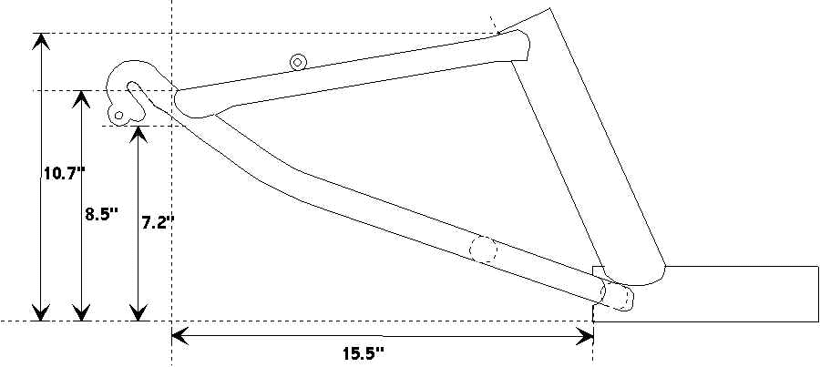
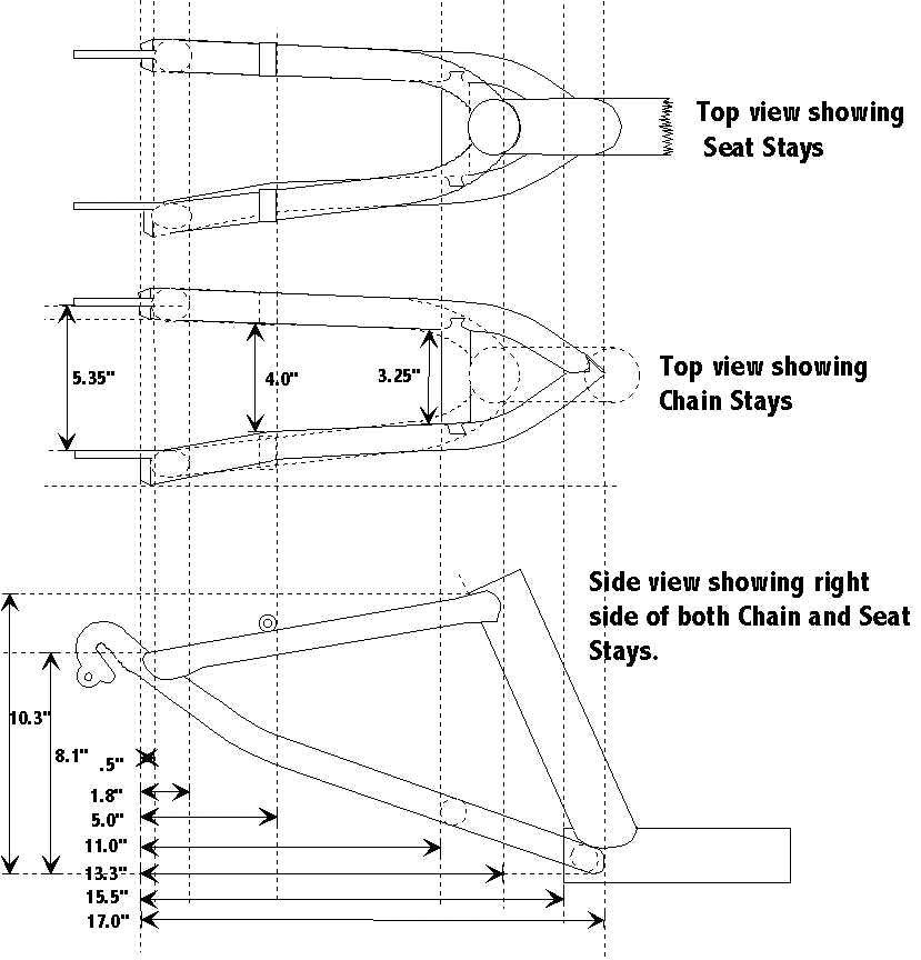
The objective of this section is take the already made subassemblies and weld them together so that the finished article appears as shown below.

Attaching the Chain Stays to the Main Tube
Take the main tube section and situate it so that both left and right cross-members are level. Place the chain stay assembly into the open rear of the main tube. Situate this assembly so that it appears as drawn above. In some cases the intersection where both chain stays are welded must be trimmed to fit correctly. In other cases the main tube may need reshaping to accommodate the stay assembly. Regardless, make the neccessary modifications so that this assembly fits properly and the alignment of the drop-outs are true.
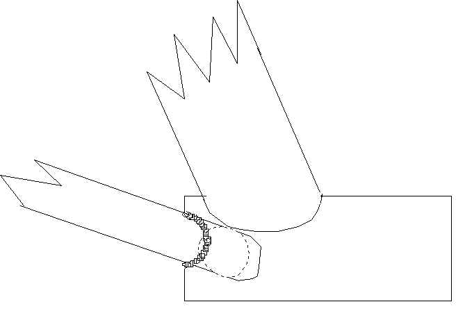
Once the assembly is situated and held in place, weld it as shown below:

Obviously, the welds made are not complete as the stays are not fully fastened to the frame yet. Using a MAP torch, heat up the bottom rear of the main tube. The heat should cover an area about 1" from the end of the tube to each one of the welds made. The temperature should be around 800° F. This effort should anneal the aluminum so that it can now be easily formed. Using a 1" rod and mallet, form the bottom rear of the main tube so that it now interfaces with the remaining bottom portion of the chain stay assembly. Refer to the illustration below for detail.

Once this contour is made, proceed to weld the remaining bottom portion of the stays to the main tube. There should be a small gap on the top of the stays and the top of the main tube. This gap is normally small and can be filled with welding rod.
Attaching the Seat Stays
Although the concept of attaching the seat stays appears an easy task, special precautions must be made to insure proper alignment is achieved. To insure the stays are properly aligned, take a spare 26" wheel (preferably the one being used for the trike) and place it into the drop-outs. Insure that the axle is fit flush to the back of each drop-out. Observe the orientation of the wheel and the seat tube; they should both be parallel. The wheel should also be pointing parallel with the main tube. Bend or adjust the stays as required. Once proper alignment is achieved, place both seat stays into position. If the stays were cut perfectly, no adjustment would be required. However, being that nothing is perfect, some adjustment may be required. Using a felt pen, place a small mark where the left and right seat tubes should be situated. Using a 1/16" drill place a hole near the inside bottom of each seat stay. This hole should be 1/2" from the bottom. The purpose of these holes is to allow gases to escape during welding. Remove the rear wheel, and insure that no stresses are built up in the stays as the wheel is removed. Situate the seat stays so that they align into the marked positions. Once secured, weld them so that the bead is completely 360° around each tube. Perform this for all 4 joints.
Fabricating the Seat Mounts
The seat mounts are fabricated from 7/16" Aluminum rod. Cut the rod into two separate 1.25" long sections. Drill a .2720" hole using a #I drill down the middle of each rod section and tap using 5/16" x 24 TPI thread. This tap thread should reach through the other end of each rod section.
Upon completion, situate the newly made seat mounts onto the seat stays as shown in previous drawings:

Since each seat mount is 1.25" in length, the ends should have a 1/8" overhang on both sides. Secure the mounts and weld them using a 1" bead on each side.
The trike frame should now be nearing completion and only requires the installation of the steering knuckle mounting plates to be complete.