Chapter 7, Part 5, Section 1
Building the Steering Knuckles
Version 3.0
Written by Rickey M. Horwitz
Notice
The material contained in this section is protected by U.S. copyright laws. Any unauthorized duplication or publication of the material contained in this section is prohibited by law.
Introduction
This section focuses on the fabrication of the Steering knuckles. The steering knuckles come in two basic configurations. The first configuration is for OSS. In this configuration both steering knuckles are identical (reverse symmetry, of course). In the USS, a second arm is used on the right steering knuckle so that it can control an aft mounted U-bar. Therefore, if OSS is desired, omit the second arm. However, if USS is desired build the second arm for the right steering knuckle.
Materials Required:
Tools Required
Building the Raw Components
Take the 1" aluminum rod, and cut two sections at 2.50" +/- .01 in length. These two sections shall be the Kingpins when finished. Using a metal lathe or a drill press with a #Q drill bit, drill a hole down the center of each rod. The hole must penetrate at 1" per each side of the cut rods. Situate both kingpins in a vice so that they are side by side. Orient the vice so that both kingpins are at a 107° orientation to the drill. Using a .875 hole saw with pilot drill, cut a 180° hole in each of the kingpins as illustrated in the drawing below.
The finished parts should look as drawn below:
Using the 7/8" aluminum rod cut two sections at 1.5" +/- .01" in length. These sections shall be the Axle Mounts. Drill a .4040 hole down the center of each of the axle mounts using a #Y drill bit and drill press. This hole should penetrate all the way through the mounts. Tap this hole using 12mm x 1.75 metric tap. If a 12mm x 1.25 is desired use a .421" or 27/64" (10.8mm) drill bit. Insure this hole is tapped straight and no misalnment occurs.
Using a drill press and a 3.5" hole saw, drill two holes in a piece of .125" thick aluminum sheetmetal. The round inside portions (disks) are used to support the Drum Brake Backplate. Using a file or drum sander, dress the edges of each of these faceplates so that they are smooth and without burs. Depending on the type of drum brake used, a hole must be made in the face plate to accommodate the brake lever axle. Refer to the drawing below.
Find the exact location and diameter of this lever and drill a hole that can accommodate it. Using a .875" hole saw, drill out the middle of the Faceplate. This hole will be used for the axle mount.
Welding the Kingpin and Axle Mount
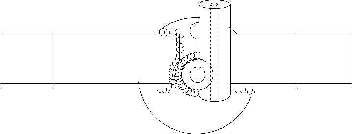
Using a spring clamp, fasten the kingpin and axle mount together. Insure that they are oriented as shown in the drawing below.
On a grounded steel table, place the setup in preparation for welding. Clean all visible area of each sub-assembly using a stainless steel brush. Recheck the setup for proper orientation. Weld a contiguous bead around the entire circumference of the axle mount.
Welding the Assembly to the Faceplate
Orient the Faceplate so that it is laying down flat (this is real easy!). Insert the axle mount into the 7/8" hole in the middle of the Faceplate. The brake lever axle hole should be pointing towards the top of the kingpin. Clean all surfaces around axle mount portion and Faceplate using a stainless steel brush. Check to insure proper alignment as shown in the drawing below. Weld the axle mount to the faceplate. All welding shall be in the inside of this assembly so that the brake assembly side is clear and flat. Depending on the type of TIG welding tip and lens, it may be impossible for a 360° bead. However, weld as much as possible.
Building the Drag Arm
The Drag Arm subassembly is used only for the USS configuration. Only one of these assemblies is required.
Note
I intended this arm to be fitted for the right side, but it is drawn as a left. It doesn't really matter which side the drag arm is on. However, if a right side is preferred, pretend the part is upside-down and fabricate accordingly.
Building the Control Arms
All Thunderbolt Steering configurations use this assembly. Therefore, a left and right arm are required.
Note
As shown, only the right arm is drawn. The drawing must be inverted for a left arm.
Putting It All Together
As shown in the drawing below, bend each of the Arms at the 45° mark. They should be at a full 90° when finished. Clean all areas around each 45° with a stainless steel brush and weld as shown.
Situate the applicable arms to the knuckle sub-assembly so that the whole assembly appears as below. Once satisfied, clean all areas to be welded with a stainless steel brush and weld as shown below. Also insure that the other side of the angle extrusion arms are welded as shown in the side view drawing.
Top View
Side View
As shown in the side view above, both angle extrusion arms are situated flush with the bottom of the Axle mount.
Installing the Drum Brake Mechanism
Some of this material is covered in the brake modification section.
Referring to the Sachs VT5000 brake backplate. This backplate requires modification prior to installation on the steering knuckle. First, the steel reinforcement lever on the backplate must be removed. The best way to remove this lever is to cut it off using a hack saw. Once this lever is roughly cut from the round backplate, use a grinder to shape it so it conforms to the flush round figure of the backplate.
Using a grinder, remove the head from the brake lever. Grind this head flat with the brake lever. Remove the brake lever from the Actuator Cam. Place the point of a punch (or small bolt) at the mid-section of the brake actuator arm axle (ground down area). Using a hammer, tap on the ground actuator axle until it recedes and separates from the actuator arm. Remove the brake lever from the Actuator Cam. It is your choice whether to remove the brake shoes from the backplate. In all cases this will be required for one set of shoes as the shoe orientation must allow the leading shoe to be placed forward.
Caution
The spring used to retain the brake shoes is very strong and cause injury if not performed safely.
The last modification required to the brake faceplate, is making the plate flush with the steering knuckle faceplate. With the brake lever removed, this assembly can be installed. Once installed, an inspection can be made to exploit any uneven surfaces that require grinding. Grind all uneven surfaces until the actuator cam barrel extends flush with the knuckle face plate. Refer to the illustration below.
Attach the brake lever to the cam axle as shown below. The orientation of the lever must be situated so that when the lever engages the brakes to the drum, it is oriented between 50° and 60° as shown below. Ideally, the lever should not surpass 45° under full deployment. During shoe wear this requirement may become an issue, so be care.
In addition, the brake lever must be bent so that it can clear the steering arm weldment. Bending can be done in a umber of ways, but prior to this, the lever must be annealed so that it doesn't crack during reforming.
Referring the drawing above, place a hole for the cable barrel. this hole is placed 1.5 inches aft of the cam axle. The specific hole size and tap depend on the cable barrel supplied with the Sachs brake kit.
Final Assembly
As may be suspected, the hole for both draglink and tie-rods were omitted. These holes are drilled when the machine is ready for final assembly.
Re-drill the bottom of the King pins. Place the entire steering knuckle assembly in a vise and re-drill using the #Q drill bit. Insure that this hole goes down straight, does not elongate and penetrates at least 1". Tap both sides of each assembly using a 3/8 x 24 TPI SAE tap.
At this point, the Knuckles are ready for painting. It's best to sand all exposed parts so that the paint can adhere to the aluminum. For quick drying, try heating the parts in an oven (200°F) prior to painting. This practice allows a much thicker first coat to be applied without runs or sags.
Assuming that the Knuckle Face Plates have been fabricated (and welded to the frame), the steering knuckle assembly can now be assembled. Using the 3/8" Rod-End Bearings, mount these into the face plate on both top and bottom. A total of four nuts are required. Place the knuckle between the two Rod-End bearings. There should be a gap between the Rod-Ends and the Knuckles measuring around 1/4 to 3/8" wide. Using the 3/8" washers fill in this gap by placing the washers evenly on the top and bottom of the knuckle assembly. Once the gap is displaced, place the 3/8" lock washers on the Cap screws, refer to the illustration above. Insert this combination through the rod-ends and washers and secure into the steering knuckle. Do the same for the opposite end of the steering knuckle. Tighten both cap screws securely (no torque specification). Remove two of the nuts securing the knuckle assembly to the face plate. Refer to the final assembly for mounting the remaining hardware to this assembly.