Chapter 7, Part 9
Final Assembly
Version 1.0
Written by Rickey M. Horwitz
Notice
The material contained in this section
is protected by U.S. copyright laws. Any unauthorized duplication or
publication of the material contained in this section is prohibited by law.
Procedure Overview
This chapter is a catchall for all open items that were not performed in previous chapters. These include the fabrication of the Derailleur Cable Stop, and drilling the holes for both steering knuckle levels. In addition, final assembly instructions including front-end adjustments have been included.
Tools Required
- 9/16" socket
- 9/16" wrench
- Adjustable crescent wrench
- 5 mm hex key (Allen wrench)
- Wooden or rubber mallet
- Whiskey
Assumptions
· You are not an idiot (even if your wife thinks so).
· The front wheels have been laced using a two cross pattern.
· You have the following components:
· Front and rear derailleur, ATB type, STX RC or better
· A rear 26" inch wheel with cluster
· Brake handles
· Handle grips
· Shifters, Bar Cons suggested
· Cables, derailleur, brakes
· Three lengths of chain
· Bottom bracket, UN51 or better
· Set of cranks w/chain rings, Forged, triple ring
Lacing the Front Wheels
Lace the front wheels using a two cross pattern. The spoke size is dependent on the type of rim. These spokes are generally 168 mm in length. This assumes an ERTO 405MM rim.
Completing the Steering Control System
Each Steering Knuckle is attached to the trike frame cross members using two 3/8" Rod End Bearings. Each of these rod bearings is attached to the ends of the kingpins. On the open threaded end of each rod bearing, place a 3/8"-24 TPI jam nut followed by a 3/8" washer. Situate the steering knuckle assembly so that it fits on to the cross member knuckle back plate. Adjust the jam nuts on both rod bearings so that the axles are perpendicular (at a right angle) to the ground. Perform this operation for the other steering knuckle as well. Place washers on the opposites sides of the knuckle back plates. Last, secure the assemblies by placing Nyloc lock nuts on all four rod bearing ends. Refer to the illustration below:
Place the front wheels onto the steering knuckles and secure them by attaching a 12 mm Nyloc nut on each of the axles. Adjust the steering knuckles using both upper and lower 3/8” rod-end bearings so that the left and right front steering knuckles appears symmetrical and that no camber exist.
Using masking tape secure both wheels so
that they are exactly parallel.
The drawing below shows the Ackerman intersections (look at the dotted
line).
Note
For clarity, the Ackerman intersections lines were drawn from the top
of the kingpin. Consequently, the
Ackerman is slightly under-compensated (2.75” aft of the rear axle) for the
error in the king pin angle.
Using the Ackerman intersection lines,
find the intersect points where the tie rods should be placed on the knuckles
levers. When the intersections
points have been carefully identified, mark each knuckle lever with a felt pen,
and drill a 5/16" hole through each of the marks.
NOTE
Clearances for the control rods may be impaired by obstacles in the
path of the rods. Spacers on the rod end mountings provide a way of
circumventing this problem.
Install the 24" tie rod as shown below using a set of 5/16" x 1" screws and applicable Nyloc lock nuts. By adjusting both tie rod-ends and Steering knuckle rod-ends, insure steering geometry has a neutral camber, and even toe-end.

The photo above shows the link rod on the opposite side
This jumbo photo shows most of the needed detail for mounting the steering rods.
Using a set of 5/16" x 1" screws and applicable Nyloc lock nuts, adjust and attach the drag link as shown above.
Note
Because of geometry differences, the exact order of the drag rods may differ. Consequently, clearance issues may force you to place the rods on top or bottom of the steering levers. This is ok.
Toe-In Adjustment
Camber and rolling resistance tend to force the front wheels outward at the forward edge. To compensate for this tendency, the front edges of both front wheels are adjusted slightly inward. This relationship is known as the Toe or Toe-In measurement. The left and right Tie Rod linkage arms maintain and control the Toe relationship of the front wheels. If this relationship is altered, excessive tire wear and poor rolling resistance shall occur. For optimum performance, the Thunderbolt uses 0 to 1/8 inch toe-end. The toe is measured at a complex orientation at 180° of both sides of the wheel as depicted on the following page.
Toe-End is: point 1 minus point 2 equals
the total Toe-In measurement
Drive Train System
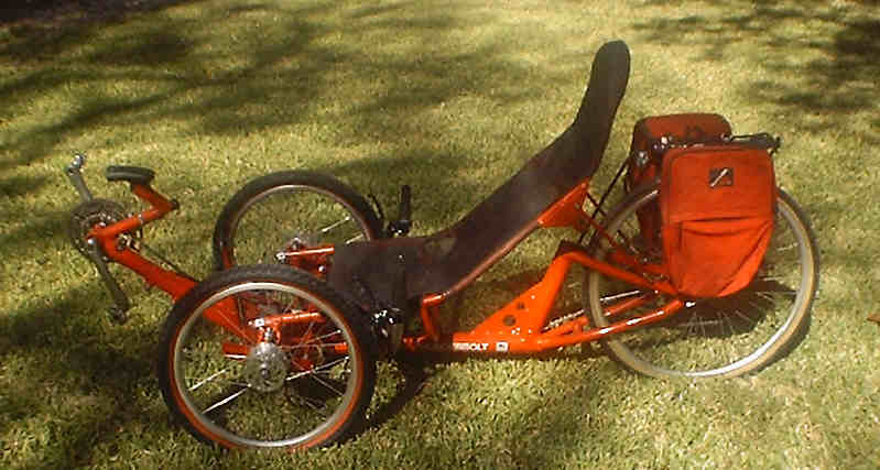
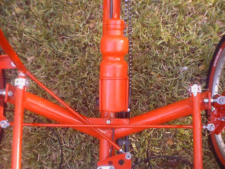
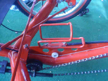
A predominant trademark of the Thunderbolt is the extra long chain. The chain is made up of 2.65 standard chains! Before, measuring the chain, the bottom bracket must be properly adjusted for the rider prior to determining the length of chain. The photo below shows how the front chain system should appear. In addition, it shows also how to mount a water bottle.
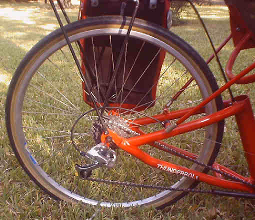
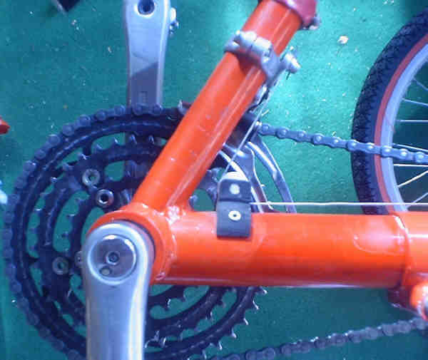
The rear of the chain can be seen in the photo below. Note the derailleur cable routing (Shimano STX RC).
The metal piece rising from the seat tube is used to support the back rack
Seat Installation
The rear seat mount uses two rod end bearings which fasten to the seat stay tubes. The forward seat section is secured by use of clamps which secure the two seat tubes to the frame. The mid seat cross section tube rest on a Delrin mount.
To secure the seat, fasten the rear rod-end bearings to the chain stays using 5/16 x 1" long screw on each end. Next, place the forward seat tubes into the applicable frame post clamps. Align and tighten as required.
Rear Derailleur Cable Stop Fabrication
The rear derailleur cable stop is mounted on the right seat mount. This part is fabricated from a small piece of delrin as specified below.
Upon fabrication of the cable stop, the part is situated on the right seat mount on the seat stay. as shown in the cross section below:
Rear Derailleur Cable Routing
Upon mounting the above derailleur stop on the trike as shown, refer to the illustration below for routing the derailleur cable to the shifter.
The cable routing is straightforward. The only bend the cabling experiences are within the cable housing. Friction is kept to a minimum. Details on the remaining routing of the cable forward of the Seat Mount have been omitted, as this is a personal preference.
Front Derailleur Cable Routing
The routing of the front derailleur cable is straightforward. Refer to the photos below for details.
When it's all done, it should look something like the photo below: