Chapter 7, Part 8
Assembling the Chain
Management System
Version 1.0 Initial Hack
Written by Rickey M. Horwitz
Notice
The material contained in this section is protected by U.S. copyright laws. Any unauthorized duplication or publication of the material contained in this section is prohibited by law.
Chain Management Overview
In earlier incarnations of the Zephyr, I employed a four chain pulley system for the chain management system. Although I heard all about the success of using Sprinkler Tubing for routing the chain, I thought the idea was crude and inefficient. As I studied the virtues of using sprinkler tubing, I became increasingly fond of the idea. Eventually, I abandon using a four pulley chain system and resorted in using polypropylene tubing for routing the passive side of the chain. Not only did this prove to reduce the weight and complexity of the chain management system, it also kept the chain clean and prevented it from derailing from the pulleys. As for efficiency, the poly tube does produce extra drag on the chain. However, keeping the chain well lubed reduces this effect making it as competitive as the four pulley system.
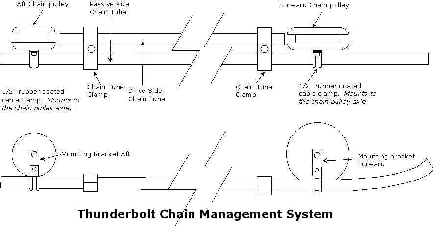
The illustration below summarizes the Thunderbolt chain management system. The system comprises of two chain pulleys (both forward and aft), two chain tube clamps, two 1/2" cable clamps, two mounting brackets (both forward and aft) and two polypropylene tubes (drive side and passive side). Of course this recipe is not complete without a handful of hardware and hard work.

Top and side view shown above
Front View Shown Above
Materials Required
Tools Required
Building the Chain Tube Clamps
The Thunderbolt trike requires two Chain Tube Clamps. The tube clamp is fabricated out of a 1"x1.5"x .35" piece of Delrin. If required wood can be substituted. The drawing for this clamps is shown below:
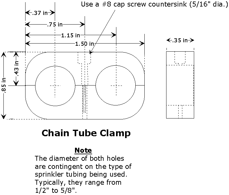
Best way to approach this part is to shape the delrin into a 1.5"x 1"x.35 rectangular piece of stock. Don't bother chamfering the edges until the end. Drill the two chain tube holes. Normally, the diameter of this hole can range between 1/2 and 5/8 depending on the type of sprinkler tubing being used. I prefer the thicker 5/8 stuff, as it remains a bit more rigid than the thinner walled tubing. Once these two large holes are drilled, drill a hole using a #29 drill bit through the delrin as shown in the drawing above (90° angle difference from the tube holes). Using a 5/32" drill bit, drill half way through the .135" inch hole (made with the #29 drill). If a cap screw is desired, a 5/16" counter bore is required as shown. The counter bore should be drilled no deeper than 1/4". Next, chamfer the part so that it appears as the drawing. Using the 8-32 tap, tap threads into the .135" portion of the hole (half the height of the stock). Using a band saw cut the piece in half as shown. You should now have Chain Tube Bracket that has no equal in detail or quality. Two of these bracket are required for each trike.
Fabricating the Chain Pulleys
It wasn't until the release of the Mk III Zephyr that I discovered the virtue of urethane wheels. Previously, I used custom machined Delrin wheels. However, I found that urethane wheels were much easier to manufacturer and lasted as long as the Delrin pulleys. I cannot emphasize the importance of hardness required for these urethane chain pulleys. I spec out a durameter of at least 88. If a softer urethane wheel is used the finished pulley will wear out very rapidly.
-Foot Note-
Being the spoiled bastard I am, I had the luxury of a complete machine shop at my disposal. Therefore, building anything was a breeze. I have since sold all this heavy equipment and I now have only basic tools such as a drill press, sanders and saws. Placing myself in this situation now give me much deeper appreciation for all these homebuilders that build all these intricate parts using simple files and saws. The same applies to chain pulleys. I had to rethink how a homebuilder could fabricate a pulley using a drill press as the only resource. The material used to create my chain pulley fabrication procedures are compiled from works of different authors. Therefore, this procedure is not a Rick original. However, the drawings and procedures are all mine.
Building a Tool Rest
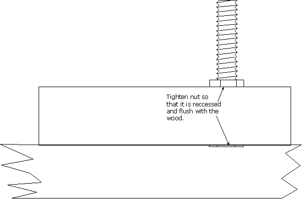
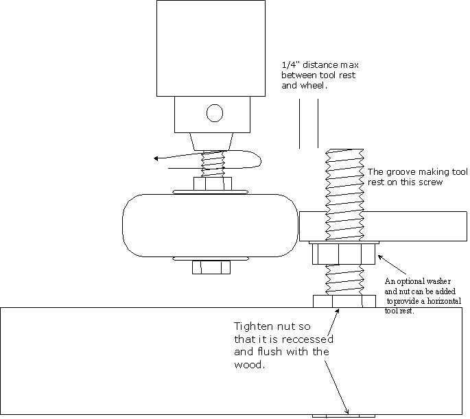
Next, we need to build a tool rest. The tool rest is built using a 2" long 1/2"x20 TPI screw, a 1/2" x20 TPI jam nut, a 1 ft section of a 2"x4" pine stock and two 4"inch 'C' clamps to keep it secured to the drill press. Take a 1 ft section of 2x4 and lay it flat (wider portion horizontal). Drill a 1/2 hole in the center all the way through. Place the 1/2" screw into the hole and fasten using the the jam nut. Secure using a wrench. Tighten so that the screw head becomes flush with the wood. The tool rest is now complete. Place the finished assembly on the drill press table and secure using the two 'C' clamps. Situate so that it appears as shown below:
Building a Cutting Tool
We need a tool for turning a groove into the urethane wheels. This tool should be at least 8" long and 1/2" wide with a negative rake. If wood lathe shaping tools are at your disposal, you can skip this section. The cutting tool should appear as shown in the illustration below.
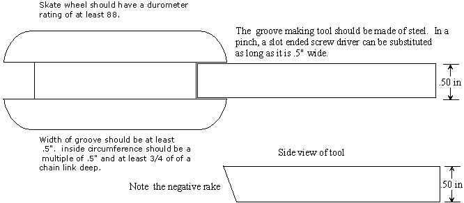
Take the urethane wheel with both bearings installed and place a fender washer on each side of the wheel. Insert the 3" 5/16 machine screw through the middle. Place a standard nut on the screw and tighten it down securely. The assembly should appear as shown below:
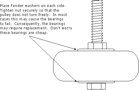
Place the remaining end of the machine screw into the chuck of a drill press. Turn on the drill press and observe the wheel. It should not wobble. If the assembly wobbles, you must correct this before turning and shaping the wheel.
Turning the Pulley
As mentioned two different size pulleys are required. The forward pulley is large and is generally made from an in-line skate wheel. The rear pulley is much smaller in diameter and is made from a skate board wheel. Both wheels are turned in the same fashion. Each is cut with a 1/2 to 3/4" groove. The depth of this groove is contingent on two aspects; the groove circumference must be a multiple of .25" and the groove depth must be at least 3/4 of the height of the chain link. The rest is up to you.
Preparing the Tubing
As you have already noticed, the polypropylene tubing comes in a helical shape that is unusable for our needs. Consequently, we need to straighten this tubing. Two popular methods have been developed to overcome this problem. Depending on your skill set and resources, the preferred method is your own choice, as both produce excellent results.
In the first method, the tube is cut to the desired length plus an inch or so. At one end of the tube the end is folded over at about an inch. Masking tape is used to hold this fold in place. Boiling water is filled into the opposite end of the tube until the tube is completely full of boiling water. Hold the tube vertically as to keep the water from spilling and the tube from bending. When the water and tubing both cool down, the water is removed. The tube should now be straight.
An alternate method is to use a long 1/2" wooden dowel that is placed inside the specified length of tubing. The tubing is heated up using a torch, boiling water, or heat gun. When the tube cools off, the dowel is removed. The tube should be straight.
Tube Cut, Trim and Shape
For the low chain tension (passive) side, this tube shall be significantly longer than the high tension side tube. The exact length is a preference, but 30 inches is the nominal. Four inches behind the forward tube end of the tube, a small bend is made so that the tube can point towards the chain rings. This bend can be made using a torch or a heat gun. The high tension side tube is trimmed at 20.5 inches in length. This piece is straight.
Building Mounting Brackets
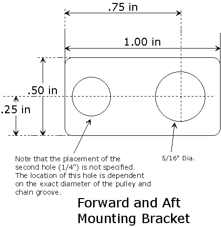
The Forward and Aft Mounting brackets are fabricated from .5" x 1" x .063" aluminum sheetmetal. The exact shape and dimensions are dependent on the exact diameter of the chain rollers and the depth of the chain groove. Therefore, final fitting will be required. The bracket dimensions appear in the figure below.
Modifying the Cable Clamps (Optional)
In some circumstances the Forward Mounting Bracket is not required. Consequently, the 1/2" rubber coated cable clamp mounting hole diameter must be enlarged to 5/16". Use extreme caution when enlarging these holes as the clamp may bind into the drill.
Pulley Axle Fabrication
The Pulley Axles are fabricated from 5/16-24 TPI, Stainless Steel All-thread. This stock is cut to approximately 3.25" inches in length. Depending on the exact type of wheel and width of nuts being used, the length of this axle may vary. The ends should be dressed as to avoid sharp edges or cross threading.
Final Fitting
When all the parts have been fabricated, we are now ready for the final fit stage. We shall refer to the overall drawing below for details. It is best to fit the chain tube clamps to both active/passive chain tubes. Once both of these clamps are in place, the tubes can be adjusted accordingly. Next, mount the chain pulley axles to the trike frame. A washer and jam nut should be used to keep this axle stationary to the frame. Install the chain pulleys(assuming the bearings have been installed). When placed on the axle, the pulleys must have sufficient clearance so that they do not rub on the frame. On each axle, install a jam nut so that it is secured against the pulley. This nut is hand tightened as to prevent the bearings from binding. The mounting bracket (or cable clamp) is placed on the axle. Insure no clearance issues exist. Last, a Nyloc lock nut is installed on the axle and securely tightened.
Conclude this section by attaching the tubes to the chain management system. Place both cable clamps over the chain tubes as shown below. Using a 1/4" nut, screw and lock washer, attach the cable clamp to the mounting bracket. Secure and adjust as required. The Chain Management is complete.
