Chapter 7, Part 5, Section 4
Building the Under Seat Steering System
Version 1.1
Written by Rickey M. Horwitz
Notice
The material contained in this section is protected by U.S. copyright laws. Any unauthorized duplication or publication of the material contained in this section is prohibited by law.
Introduction
In this part hardware assemblies comprising the Under Seat Steering (USS) System will be fabricated. In addition, a modification shall be made to the main tube section of the frame, as a means to securely mount the 'U' bar under the seat.
Materials Required
Tools Required
Modifying the BMX Steering Stem
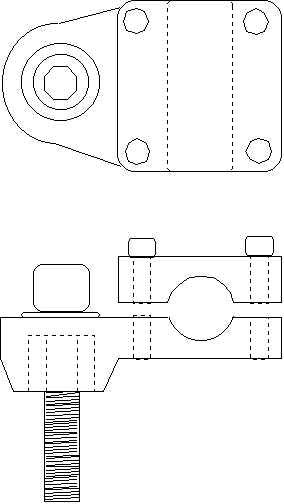
Building the Under Seat Steering system requires the correct type of BMX Steering stem. This assembly is characterized by having four bolts to fasten the handlebar to the stem. Additionally, this assembly should have the stem in close proximity to the handlebars. A typical BMX steering stem is shown below with the required modification.

The first thing that needs to be done is removing the steel post out of the aluminum base. This is not an easy task as this post has been press fitted under a tremendous load. Best way to get it out is by drilling a 3/8" hole through a cross section of the post. This hole is under an inch from the aluminum base. See the drawing below:
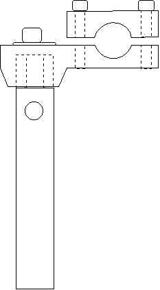
Place the aluminum base in a vice so that the jaws barely contact the post and that the base rest on top. Using the existing long bolt that came with the steering stem, drive the bolt downward using a hammer. Eventually the post will work itself free from the base.
After the stem is removed, there should be a big hole in the bottom of the base. Shape a piece of delrin stock so that is fits tightly into this hole (it's a great time to have a lathe). Allow a .25 of delrin to extend out the bottom. Place the aluminum base in a vice and insure that it is aligned properly. Using a drill press, drill out a 7/16" hole through the center.
Building the Steering Arm
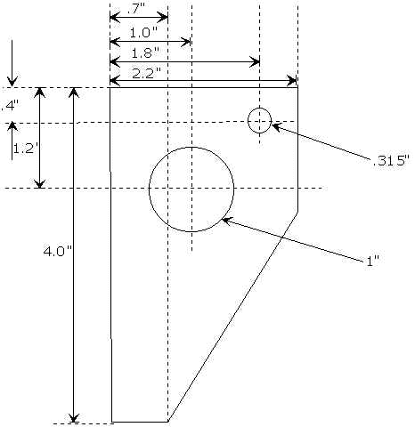
The Steering arm is constructed out of 1/8" (.125) plate aluminum. The drawing for this part is shown below. This part is designed to interface with the BMX steering stem as shown above.
NOTE
Every Steering Stem is different. Consequently, the mounting holes for each type of steering stem differ, so I left them out of the drawing.
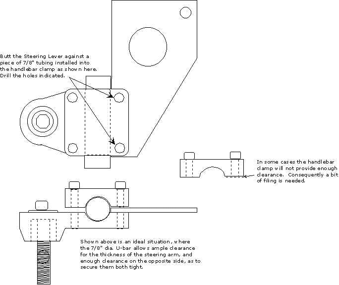
Situate the newly completed Steering Arm into the handlebar clamp as shown below. Since steering stems come in all varieties, we must measure and mark the exact distance and size of the holes on the handlebar clamp. Using the holes as a template ( the bolts have been removed, right?) mark the arm so that it can be drilled. Normally, the bolts used on these BMX type steering stems range from 5/16" to 3/8". Once drilled, check the arm in the steering stem to insure that the two bolts holes can be installed. A perfect fit is when top clamp fits firmly down on both steering lever and handlebars while maintaining parallel with the lower casting.
Attach the Steering stem into the frame. This means that the 7/16" cap screw is secured down until the movement of the stem is restricted. check the clearance between the frame and the steering stem. This clearance must be minimized as to provide maximum strength. However, insure that the tie rod can attach and move without clearance issues prior to any rework. Once satisfied with all issues, remove the 7/16" capscrew and place some blue lock-tite and refastened.
Cutting, Drilling and Tapping the Steering Rods
There are two steering rods, the Drag link and Tie-Rod. 17.5" for the Drag Link section and 24" for the Tie Rod. These lengths are fairly liberal and you may have to trim them down a 1/4 to 1/2 inch. Each rod end is drilled out using a #I drill bit. The drill must penetrate at least 1.5 deep. Each hole is tapped using a 5/16 x 24 TPI SAE tap. The threads should go done at least 1.25". Upon completion of all four ends, remove all burrs from the corners.
Bending the 'U' into a 'U' Bar
Using the 42" section of 7/8" dia. aluminum tubing measure and mark a 7" distance from each end. Using the 3/4" conduit bender place the hook so that is faces towards the end of the tube. Align the arrow to the 7" mark and bend to a 90°. Reinstall the bender so that it faces toward the opposite end of the tube. Again, align the arrow to the 7" mark and bend the tube so that it resembles a 'U" shape. In some case you may want added clearance between the U bar and seat or you may want to position the U bar further away from the front wheels. This can be accomplished by marking at 6" inches vise 7". Examples shall follow on next update.
Note
Because the bender handle interferes with the opposite side of the tube, the 'U' bar may resemble a pretzel. After both bending are complete straighten and align the 'U' bar by hand.