Chapter 7, Part 5, Section 3
Over Seat Steering Fabrication
In-Process
Written by Rickey M. Horwitz
Notice
The material contained in this section is protected by U.S. copyright laws. Any unauthorized duplication or publication of the material contained in this section is prohibited by law.
Introduction
This section focuses on building an Over Seat Steering System (OSS). The steering assembly is extremely simplistic and light weight, as it consist of a single handled tiller system mounted on a universal joint (U-joint). On the bottom of the U-Joint a bell crank is mounted to the cross-section of the frame. On the opposite end of the bell crank lever, both the steering tie rods are mounted.
Required Materials
7/8" x .065" Aluminum Tubing, 3 ft long.
3/8" Universal Joint used for standard socket/ ratchet.
1" aluminum bar stock.
1" Seat Clamp, two each.
1" x .065" Aluminum Tubing, 8 inches long.
4" x 1.5" x .250 Aluminum plate.
Overview
The OSS Steering Tiller is preferred where weight constraints and high performance is demanded. Although OSS can be easily adapted to the 114° cross member frame, the proximity of the Tube Collet may come close to the riders crouch making this steering type uncomfortable. On the 90° Cross member frame, the OSS tube mount is placed a few inches forward making it a desirable if not an overall choice for both comfort and performance.
One of the significant reasons why the OSS configuration is lighter is due to the simplicity of the steering linkage configuration. Instead of using two long steering control rods, the system uses a dual draglink system (as shown below) mounted to a simple bell crank. The bell crank connects to a Tiller handle using a universal joint. This precludes the use of a heavy steering stem and associated hardware. In theory, this OSS system saves approx. 12 oz of weight as compared to a USS configured trike.
Fabrication
The steering mechanism used for this configuration is a modified 'T' bar. The 'T' bar is assembled from three pieces of 7/8" OD aluminum tubing as shown in the drawings below. The two tubes that make the handle bars, are mitered at 80° or 100°. These two pieces are then welded to the third center tube as depicted. To simplify, a single cross tube can be used instead of the two handle bar tubes. This single cross tube is bent to 20° and welded at the middle to the center tube.
The exact lengths and angles shown above can be deviated to match specific needs.
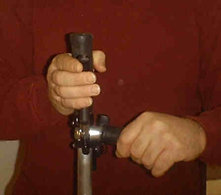
A Tube Collet is provided to allow vertical adjustment of the 'T' bar. The Tube collet accepts the 7/8" steering tube of the 'T' bar. A 1" seat clamp is used as a pinch bolt to keep the 'T' bar stationary. This assembly is shown below as a photograph with the Universal Joint attached. In addition a drawing is rendered showing the critical dimensions.
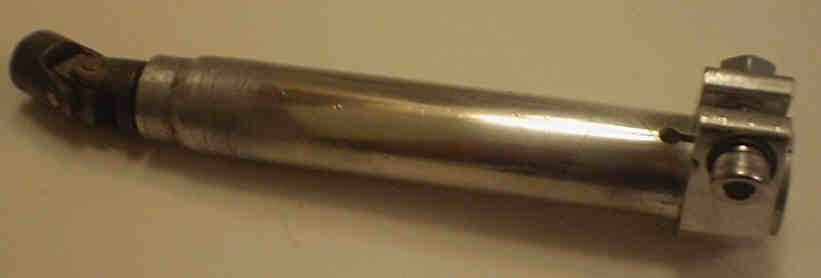
![]() More to come.
More to come.
On the lower portion of the steering mechanism is a universal joint that allows the steering assembly free 360° rotation. This universal joint mounts to the bell crank and OSS Mount collet. For this application, we use a standard 3/8" universal used for a socket set. This universal joint must be modified to reduce the amount of torsional play. The U-Joint and modifications needed are shown below.
After the U-Joint is modified, a detent must be made on the lower base to prevent it from rotating under load. Refer to the drawing below for details:
The Bell crank is attached to the universal joint, left and right tie rods, and to the trike frame. The bell crank assembly is shown below.
Next update I'll show how to build the upper and lower collet assemblies. The topic to keep in mind is 'broaching'. Stay tuned!!!!
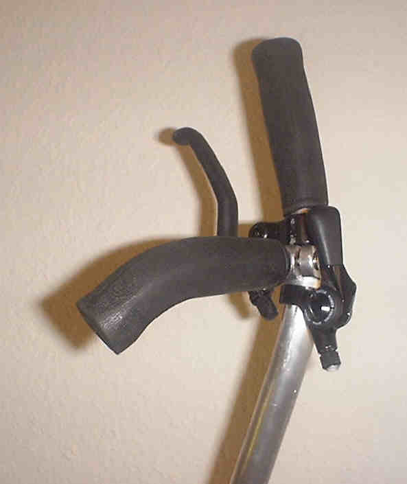
Club Tiller
The Club Tiller is scheduled for use on the upcoming Z-4 and T2000 series trike. The uniqueness of this device classifies it as valuable intellectual proprietary (even though many would ask why). Consequently details on how this device is fabricated will not be given away. However, photos of this steering system is shown below:
Brake Linkages
All the trike manufacturers have ignored the importance of implementing a working brake linkage system. Whether it wasn't a necessity or they just haven't figured it out yet, I feel reluctant to disclose this valuable proprietary technology. Therefore, below is a picture of a Quasi-Pull linkage system. Study the drawing and fill in the blanks.