Chapter 7, Part 4
Hub Modification for Stub Axle Usage
Revision 1.2
Written by Rickey M. Horwitz
Notice
The material contained in this section is protected by U.S. copyright laws. Any unauthorized duplication or publication of the material contained in this section is prohibited by law.
Note
During this discussion I use both metric and SAE measurements. The reason is obvious, we Americans are still stuck with SAE while the majority of bicycle components are metric.
Introduction
Bicycle hub axles are designed so that the frame dropouts support each axle-end. Obviously, this poses a grave concern, as a tricycle requires that a single ended axle support each of the two front wheels. Modifying an existing bicycle hub is a very challenging issue for the first time trike builder. For this reason I have created instructions for modifying a standard bicycle hub for single ended axle (or commonly referred to as the Stub Axle). Armed with this information, the home builder or frame builder enthusiast shall discover that this hub modification is actually an easy operation.
The diameter of a conventional bicycle hub axle is normally too small for a stub axle. These axles are commonly 10 mm in diameter. For a stub axle, the diameter is increased to 12-mm or greater. This added diameter thickness is required because the axle is supported on a single end and undergoes a tremendous amount of cantilevered force. It should also be mentioned that the longer the axle, the more likely it is to flex and place additional stress at the axle steering knuckle termination.
Stub axles are constructed of carbon steel. Experimentation has suggested that #5 hardness is recommended as it is strong enough to retain its elastic properties during overstressing and does not break easily. High carbon steel is not suggested, as it is brittle, having a tendency to crack rather than bend when overstressed. Stub axle fabricated from 4130 CroMo are also recommended.
The nominal length of a 12 mm axles when used with a Sachs VT500 drum hub is just under 6 inches in length. A 12x 1.25 (or 1.75) pitch thread is cut 1.5 inches down the length of one end of the axle, while the other end is threaded 1 inch with a 12.x1.25 pitch thread. All-Thread can be substituted if it consist of the same properties as a #5 hardness fastener.
The increased diameter of the axle may require larger bearings for the hub. Therefore, the hub must have provisions for bearing replacement. If a different size bearing is required the bearing cups must be removed from the hub. Once removed, a suitable cartridge bearing may be substituted. However, the hub may require machining to accommodate the new bearing size.
If the bearing cups are not removable, do not despair, the conventional cup and cone bearing may be salvageable. In order for this option to qualify, the cone must be able to accommodate a larger diameter axle. Additionally, once the cone is bored to the desired size it must be tapped to the threaded axle as to prevent it from spinning. Therefore, it is important that the cone is drilled undersize to accommodate a thread e.g., for 12-mm x 1.25, a .421" or 27/64" (10.8mm) drill hole size is required. Obviously, the builder must determine if the cup can accept the larger bore. In some cases the enlarged bore may interfere with the bearing race. In this case, saving the cup and cone (or hub) is not an alternative. Another obstacle is the hardness of the cone. In many experiments I have conducted, the cones required annealing prior to machining. Consequently, the cones required a post heat treating to make them hard again. Last, check the cups, as they may also need boring to accept the larger 12-mm axle.
Summary
The hub assembly must meet the following criteria for stub axle modification:
Many specialty hub companies including Phil Wood and American Cycle Systems have hubs designed exclusively for stub axle usage. Insure that the desired hubs can accept a 12-mm axle.
Sachs VT 5000 Brake Hubs
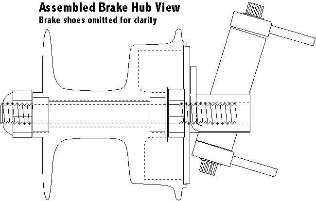
The Sachs VT 5000 Drum Brake hub is the most popular hub for tricycle design. The hub only requires that the bearing be replaced to accomadate the larger 12 mm axle. However, the Back Plate Assembly requires major modification so that it can properly interface with the Steering Knuckle assembly. When the hub and steering knuckle is complete the assembly should appears as shown below:
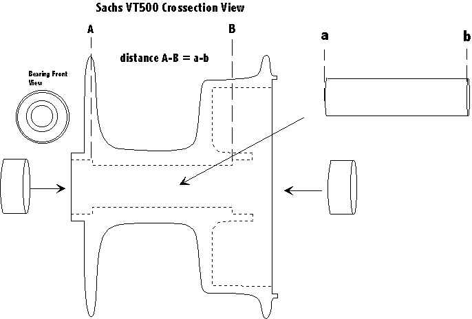
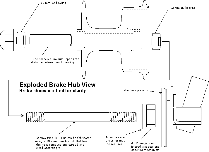
For modification, the existing axle assembly (including bearings, cones, jam-nuts and washers) must be disassembled and removed from the hub. Upon removal, disassemble all axle related hardware from the Back Plate assembly. Take the hub and carefully remove the bearing cups out of the hub journals. This can be accomplished using an arbor press and cylindrical object to evenly force the cups out without destroying the bearing bores. Upon removal, install cartridge bearings (28 mm OD, 12-mm ID @ 8-mm wide) in both ends. A tubular spacer is required that is installed between both bearing. This spacer prevents the bearing from binding during side loading. Additionally it allows the retaining nut to be tightened without damage to the bearing assembly. Refer to the illustration below for the dimensions of this tube. When installing the cartridge bearings, use the arbor press to insure that these bearings are pressed evenly into the hub bearing bores.
Remove both brake shoes by removing the retaining clip from the stationary brake shoe axle. Locate the top mounted shoe (this shoe is mounted closest to the retaining clip). Using a screwdriver, work the blade in between the aforementioned brake shoe and the actuating cam. Lift the brake shoe using the screwdriver so that it rests over the retaining washer on the cam. Lift the shoe on the opposite end (stationary axle). Again, work the brake shoe so that it eventually clears the cam retainer, be careful not to place too much stress on the brake shoe as it could break at the stationary end. Once the shoe clears the Cam retainer, the spring should disengage allowing easy removal. Re-assembly will require more patience. Removal of the lower brake shoe should be effortless.
Remove the brake Actuator Arm. The actuator arm is stamped onto the actuator Cam axle. To remove it, the area on top of the actuator arm must be ground so that it is completely flush. Place the Back Plate into a vice. Close the jaws so that both cam and stationary axle barely clear. The Back Plate should fit squarely on the vice now. Place the point of a punch (or small bolt) at the mid-section of the brake actuator arm axle (ground down area). Using a hammer, tap on the ground actuator axle until it recedes and separates from the actuator arm.
Remove the Back Plate Arm. The back plate arm is an integral part of the back plate that holds it stationary during braking. Consequently it must be carefully cut off the back plate. This can be performed by making a straight cross-cut that clears the round back plate without damage. The cut can be contoured to the round back plate by using a grinder.
Increase the Back Plate axle hole diameter. This hole is 10-mm in diameter. Increase this diameter to 12-mm.
Note
The 12-mm hole must be completely centered. Proceed with caution.
Grind the Back plate flush. The back plate shall be mounted to a face plate on the Steering knuckle assembly. Consequently this surface (excluding the cam axle bushing) must be completely flat. The best method is to grind out all the high areas using a grinder. To achieve a flat finish, use a belt sander. Refer to the photo below:
Re-assembly is performed in the reverse order in which the back plate was disassembled. Replacing the brake shoes is challenging, but can be done with a bit of diligence and patience. Fortunately, the back plate must be installed into the Steering Knuckle Assembly prior to final assembly. The remaining assembly requires the completion of the Steering Knuckle, please refer to this section for closure.
Sturmey Archer builds a drum brake hub that is already modified for stub axle usage. The hubs are sold in pairs and retail for about $200.00. Although I have not received my set yet, my preliminary findings indicate that this is the ultimate choice. The aluminum back plate and removable brake arm make this hub the easiest way of adapting a high quality braking system to a trike. For technical information about this hub, refer to the exploded drawing below:
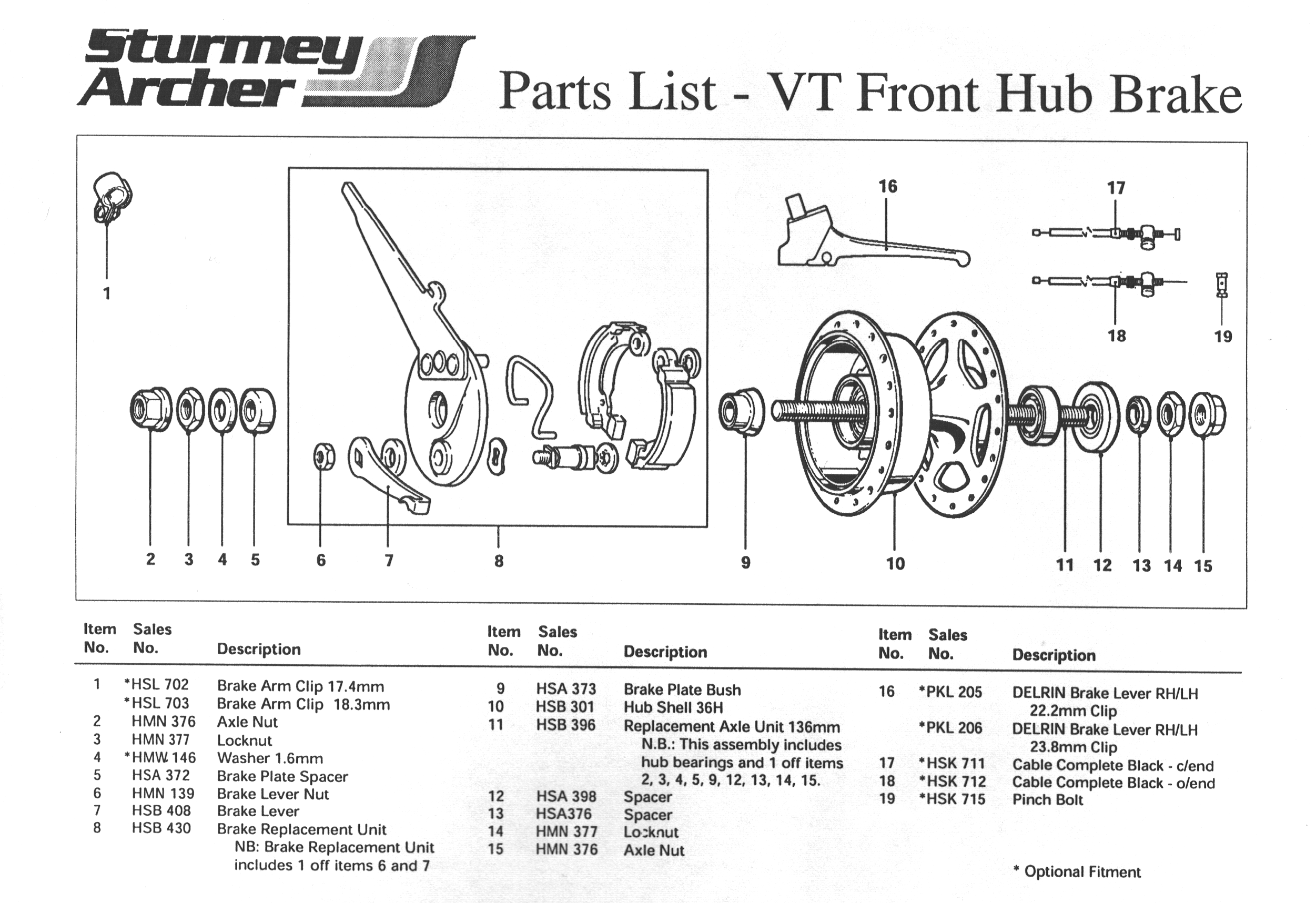
Modifications are not specifically known at this time. From the preliminary drawings only the back plate appears minor modifications.
Remove the Back Plate Arm. Unlike the Sachs, the SA elite uses a riveted arm on the back plate assembly. This can be easily removed by drilling each of the two rivet out. The holes in the back plate can serve as mounting holes required by the steering knuckle assembly.
Building the Steering Knuckles
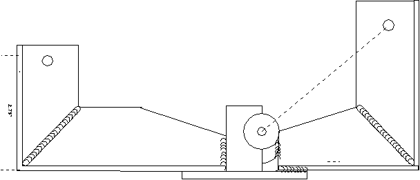
The Steering knuckles are one of the most difficult parts to manufacturer, as they comprise of several parts fabricated with near-precision accuracy. To assist in building these parts I have included assembly drawings and procedures that make this assembly as easy as possible. Since several configurations of the Thunderbolt exist, you should make your choice at this time if you desire Over Seat Steering or Under Seat Steering. Once determined, go to Part 5, Section 1 for Steering Knuckle assembly instructions.
Preview of the Steering knuckle assembly below: